
In the last chapter, we have given a brief overview of the basic principles and the design of blueprints. Now it is time to dig into the implementation. In detail, we will cover the following topics:
- First, we will show how to create blueprints and configure the basic settings.
- Then, we will dive into how to setup the provisioning of virtual and cloud machines. The amount of work needed for setting up your blueprints varies based on the kind of provisioning. While setting up provisioning based on vSphere is quite easy, other types of provisioning such as Linux kickstart or WIM provisioning can take a lot of time to implement.
| No more physical machine templates in vRealize Automation 7
In prior versions, vRealize Automation supported the provisioning of physical machines. Most commonly, they were used for legacy reasons or if virtual or cloud provisioning was not possible anymore (there was still support for HP iLO, Dell iDrac and Cisco UCS). In the new version, this is no longer supported anymore. |
9.1 Blueprints – basic settings
vRealize Automation supports a wide range of hypervisors, virtual platforms and cloud providers. For all these systems, different kinds of blueprints exist. However, they share a common range of settings. First, we will describe all the basic properties of blueprints and how to configure them and then later we will cover the configuration details.
To locate the blueprint page, we simply have to navigate to the Design > Blueprints page (with the current release, blueprints have been moved away from the Infrastructure tab). When setting up a blueprint, perform the following steps:
- On the Blueprint page, click on the [+ New]
- With the New Blueprint modal dialog opened (see Fig 1), provide a Name for the blueprint.
- Based on your provided name, vRealize Automation automatically assigns a permanent, unique ID to this blueprint. Review the ID and change it if needed.
- Provide a Description for your blueprint.
- Specifying Archive (days) implies that the machines are not automatically destroyed when the lease expires. They will instead be switched off and remain turned off until the archive period expires. Only after the archival period expires, the machines get deleted. If you don’t specify a value, a machine gets immediately destroyed once the lease time is over.
- The properties Lease (days) Minimum and Maximum can be used to configure how long a machine can be used before it gets destroyed.
- Click OK to end the wizard (we will discuss NSX and the properties later on).
| Hint: Blueprint description
While the description field is optional, it is nevertheless highly recommended to enter some meaningful information here, as this text will appear in the service catalog. The description text should be consistent across all blueprints. It should include information covering the machine’s installed software, such as operating system, installed tools (e.g. VMware tools, guest agent or Puppet) or any other custom software. By providing a meaningful description, the self-service catalog will become much more intuitive to end users. |
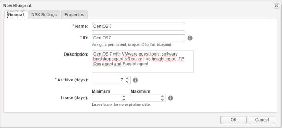
Fig 1: Blueprint wizard
Now, after having opened the blueprint designer, let’s discuss how blueprints can be created. The designer works pretty easy: Choose a category from the left pane, drag and drop an element from the item list to the design canvas, select the item on the canvas and configure its properties. If some elements are in relationship with each other, just connect them with a line (see Fig 2).
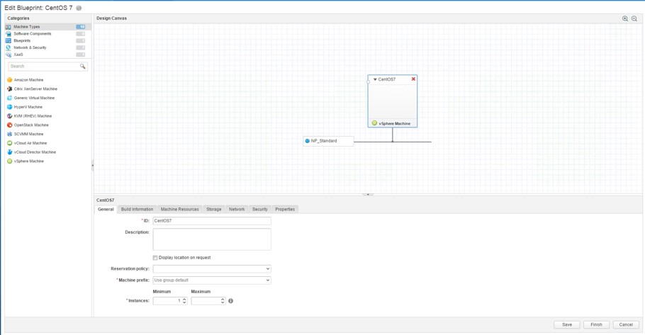
Fig 2: Blueprint designer
The most important item is certainly the vSphere machine template, so a discussion how to configure that is certainly useful.
Altogether, when selecting the elements, we can see that there are six different tabs:
- General for the basic settings.
- Build information for configuring the provisioning workflow.
- Machine resources to setup the hardware of the machine.
- Storage to configure the hardware drives and associate storage reservation policies.
- Network for associating network profiles.
- Security
- Properties to override standard values within the provisioning workflows and provide additional meta-data.
9.1.1 General
The General section lets you specify the following settings:
- The ID of the machine.
- The
- If you check the option Display location on request, end users will be able to see to which ‘datacenter location’ a machine is provisioned to.
- vRealize Automation needs a machine name to provision a machine (we have already discussed machine prefixes in the last chapters). If you are ok with the business group’s machine prefix, you can keep the default value, otherwise you’ll have the possibility to override this setting.
- In addition, you can specify a Minimum and a Maximum amount of instances that can be deployed.
| Hint: Display location on request
The blueprint allows users to see the location of the datacenter when they are requesting a machine from the service catalog. However, in order to configure this, some additional work needs to be completed. Firstly, we must log on to the IaaS component server. With the vRealize Automation website still running, navigate to the vRealize Automation website directory (usually %SystemDrive%\Program Files (x86)\VMware\vCAC\Server\WebSite\XmlData). Then, open the file ‘DataCenterLocations.xml’ in an editor. We must add the following code fragment, for each of the locations we have: <CustomDataType> <Data Name=”Nuernberg” Description =”Nuernberg Datacenter”/> </CustomDataType/> After having saved the file, we must restart the Manager Service. Finally, we can associate a location with our compute resource. Navigate to Infrastructure > Compute Resources > Compute Resources, edit our resource and choose a location for that object. |
9.1.2 Build information
There are a lot of different ways to provision machines – depending on the type of blueprint. We will discuss these provisioning workflows once we have finished our basic discussion.
9.1.3 Machine resources
This tab is pretty easy to configure, so there is no need for broadly discussing it: Just specify minimum and maximum values for the CPU, memory and storage.
9.1.4 Storage
The table on this tab is prefilled based on your configuration on the build information tab. In addition, you can associate your disk drives with a reservation storage policy. Also, it is possible to specify a drive letter / mount point for your drives. However, consider that this requires the guest agent to be working correctly in your templates in order to be fully-functional. The storage settings are depicted in Fig 3.
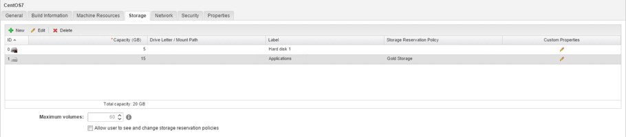
Fig 3: Storage settings of a machine template
9.1.5 Network
Setting up the network on a blueprint is also a new feature due to the new converged blueprints capabilities. However, when you initially configure a machine template, no network components are configured, so you have to drag a network component onto the canvas and configure if for your network adapter. Remember, in chapter seven we have already talked about external network profiles, so it is now time to use them (in case you have not configured them in advance, close your blueprint and configure them before you proceed with the blueprint:
- From the toolbox on the left side, choose the Network & Security category and drag the Existing Network component onto the canvas.
- Select the component and within the properties section, click on the button within the Existing network user control to associate your component with your existing network profile.
- Review the other settings on the General, DNS/WINS and IP Ranges
- Once again, select the machine template and then click on the Network
- Click on the [+ New] button and select your network interface from the list of available network interfaces.
- If you have a DCHP server configured, change the Assignment Type to DHCP. If you have your network profile configured to perform IP address management capabilities, change the Assignment Type to Static IP and leave the Address empty. Alternatively, you can assign a static IP to the network device. Once you have saved the interface, you will see that your machine template and network profiles are getting connected on the canvas (see Fig 4).
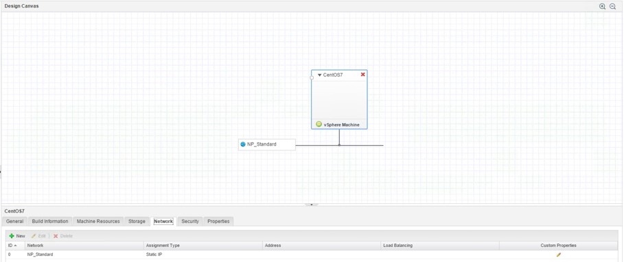
Fig 4: Network settings of a machine template
9.1.6 Security
The security settings are all related to NSX, so we will skip the discussion here and come back to it after having discussed NSX in a later chapter.
9.1.7 Properties
The Properties tab is used to override the default settings related to the lifecycle of a blueprint. As discussed, every machine passes through different stages during its lifecycle. It begins with the request and approval of a machine. Once a machine is approved, it will be provisioned and managed by a user. At the end of the lifecycle, it will have expired, been archived and been fully destroyed. These stages also represent points in time where additional behavior can be “hooked” in. There are plenty of use cases, for example:
- Joining the machine to an Active Directory domain after provisioning.
- Reducing the number of cores per socket, in order to lower licensing costs.
- Invoke a script on the machine after the provisioning has taken place in order to install additional software.
- Contact an IPAM tool in order to obtain an IP address before provisioning.
Technically, custom properties are fundamentally only a collection of key-value pairs. This is a quite generic approach, but very suitable for basic customizations. We will address custom properties in a later chapter in detail, however, to gain a certain level of understanding, let’s provide two examples:
- The hostname custom property overrides the default machine prefix, so that a user can enter the hostname at the point of request.
- There is a custom property to define the vCenter folder, where a provisioned machine should be placed in.
When creating custom properties, the following information is required:
- The name of the property.
- The value of the property.
- Optionally, you can define if the value of the custom property should be encrypted.
- The option whether the custom property should be static for all instances of a blueprint or if the value should be provided by the user when he requests the machine (Overridable).
- Additionally, you can configure if a custom property should be visible to the end user during request time (this helps to show some additional meta-data to the end-user) by activating the Show in Request checkbox.
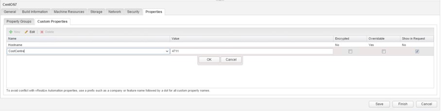
Fig 5: Configuring custom properties on a machine template
Fig 5 shows the configuration of custom properties on a machine template.
Adding property groups
In most cases, you would like to add not just a single custom property to a machine template, but a set of different custom properties to your blueprint (the custom property documentation covers more than 70 pages). As adding custom properties to blueprints can be quite cumbersome, vRealize Automation uses property groups (formerly called build profiles) to group custom properties. Once defined, you only need to add the property group to your blueprint and all the contained custom properties will be applied.
Property groups can be created by performing the following steps (see Fig 6):
- Navigate to the Administration > Property Dictionary > Property Groups
- Click on the [+ New] button to create a new property group.
- Assign a Name for the property group.
- Provide an ID.
- Configure if the property group should be visible for all tenants or only for the current tenant (Visibility).
- Provide a Description for the property group.
- Enter all the custom properties that should belong to the property group.
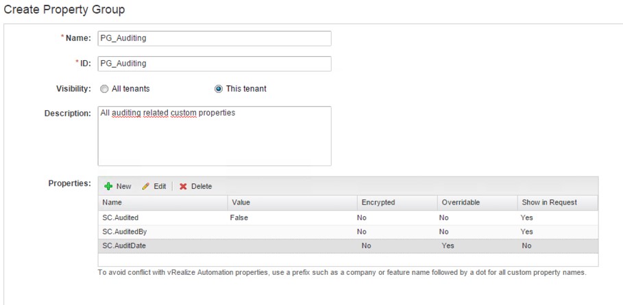
Fig 6: Creating a property group
Once you have created a property group, you can add it to a blueprint:
- Within the Property Groups tab, click on the [+ Add] button and select the property group to be added.
- Click OK.
It must be noted that it is possible to add the same custom property to the machine template if it is part of several property groups and those property groups are added to the blueprint. If these custom properties have been configured with different values, vRealize Automation will gather the value from the property group with the highest priority. You can change the priority of a group by clicking on the Move Up and Move Down button within the property groups’ table header. The configuration
of a property group is shown in Fig 7.
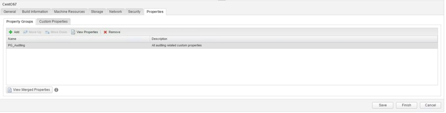
Fig 7: Adding a property group
| Custom properties at different levels
In addition, custom properties can also be placed on other items than blueprints – we have seen that in the last chapters – for example, on reservations or business groups. When vRealize Automation provisions a machine, it merges all these custom properties from these different entities and creates a list of merged custom properties that effectively are applied during the provisioning workflow. However, having custom properties placed on different levels could sometimes be confusing, as without the necessary carefulness wrong custom property values could be used – just because a custom property was defined at a certain level that you did not take into consideration. |
In addition to this, if you are using vSphere, there is an additional custom property to be configured, i.e. the operating system must be set:
- Switch to the Properties tab and create a new property.
- Name the custom property VirtualCenter.OperatingSystem (please pay attention, custom properties are case-sensitive).
- Provide the correct value for your operating system (e.g. windows7Server64Guest for Windows Server 2008 64 bit). For other operating systems, please take a look at the vSphere documentation for a complete list of values.
- Click the Save
| Hint: Attaching CD-ROM
There is another custom property called VirtualMachine.CDROM.Attach that must be added and set to true. However, this is not sufficient. You still have to configure vRealize Automation Orchestrator to use the workflow Mount CD-ROM as a new action in vRealize Automation. We will cover workflows in a later chapter. |
Allowing RDP Connections for Windows machines
Most likely – if you want to deploy Windows machines – your users want to use RDP to connect to their virtual machines. Besides entitling users to do so, you also have to add a set of custom properties to your machine template, which are shown in the following table:
| Custom property | Description | Required |
| RDP.File.Name (required) | Specifies an RDP file from which to obtain settings, for example My_RDP_Settings.rdp. The file must reside in the Website\Rdp subdirectory of the vRealize Automation installation directory. | X |
| VirtualMachine.Rdp.SettingN | Configures specific RDP settings. N is a unique number used to distinguish one RDP setting from another. For example, to specify the Authentication Level so that no authentication requirement is specified, define the custom property VirtualMachine.Rdp.Setting1 and set the value to authentication level:i:3. Use to open an RDP link to specify settings. | X |
| VirtualMachine.Admin.NameCompletion | Specifies the domain name to include in the fully qualified domain name of the machine that the RDP or SSH files generate for the user interface options Connect Using RDP or Connect Using SSH option. For example, set the value to myCompany.com to generate the fully qualified domain name my-machine-name.myCompany.com in the RDP or SSH file. |
Fig. 8: Custom Properties for RDP Settings
| Internet Explorer Enhanced Security restrictions
Note: If you are using Internet Explorer with Enhanced Security Configuration enabled, you cannot download .rdp files. |
In addition, there is another step to be taken: We have to create a custom RDP file on the IaaS Manager Service Server:
- Log in into the vRealize Automation IaaS Manager Service Server as an administrator.
- Navigate to the vRealize Automation directory (usually C:\Program Files (x86)\VMware\vCAC\Server) and then into the RDP
- Copy the file Default.rdp and rename it to Console.rdp in the same directory.
- Modify the file according to your needs.
- Copy the Console.rdp file to the Website\RDP
Cleaning up Active Directory after de-provisioning
Joining a machine to Active Directory using guest specifications is quite common when deploying machines. On the other side, when de-provisioning a machine, Active Directory entries should also be cleaned up. This can be automated by adding the following custom properties as well:
- Plugin.AdMachineCleanup.UserName: The Active Directory account user name.
- Plugin.AdMachineCleanup.Password: The password of the Active Directory account.
- Plugin.AdMachineCleanup.Delete: If set to true, machines will be deleted, if set to false, machines will be disabled.
- Plugin.AdMachineCleanup.MoveToOu: Moves the account to an OU after de-provisioning. The OU must be entered in the format: OU=newOU, DC=vra, DC=lab.
- Plugin.AdMachineCleanup.RenamePrefix: Renames the machines by adding a prefix.
| No Action tab anymore
In former versions of vRealize Automation, there was an Action tab as well. It helped to configure the list of “possible” actions on deployed items that users were able to perform. However, those actions were somehow overlapping with catalog entitlements, which led to confusion among administrators, so actions were removed from blueprints |
9.1.8 Setting up dependencies
If you configure more than one machine as part of a blueprint, you might want to define dependencies regarding the order of the components of your blueprint (i.e. in which order will the components be set up). For example, a common scenario is to first create an isolated network, then a database server and later on a web front server. You can implement such an ordering by connecting your virtual machines by linking your components:
- Click on the circle within the machine that is dependent on another machine.
- Connect the line with the component that should be deployed first.
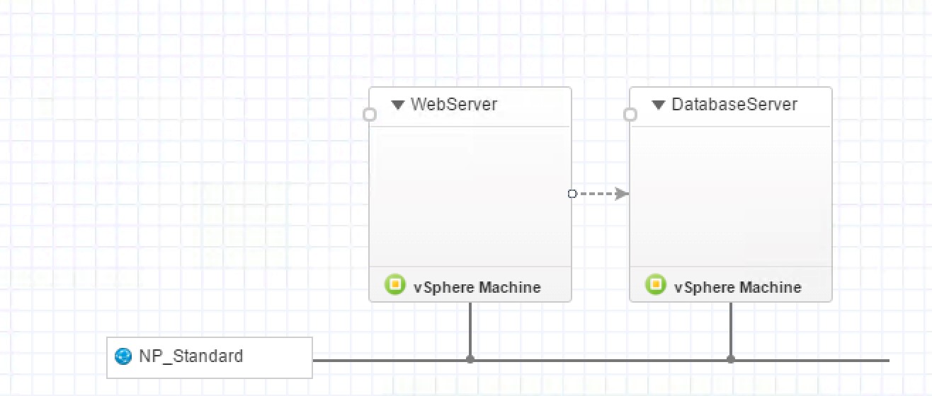
Fig 9: Setting up dependencies
A simple scenario is depicted in Fig 8. When a blueprint is deployed, vRealize Automation will first create the database server and once this is finished, will continue with the web server. However, take into consideration that vRealize Automation does not take a look into the virtual machine at provisioning time: If you have the requirement that the web server should only be deployed once the database is fully working in your database instance (assuming that you have a script within the instance that installs the database after provisioning), there is no built-in feature in vRealize Automation to handle such a scenario.
9.1.9 Publishing a blueprint
Once a blueprint is created, there is a final step required before we are able to add it to the service catalog: it must be published. Publishing involves the following steps:
- Navigate to Design > Blueprints.
- Select the blueprint to be published and click on Publish.
9.2 Provisioning of virtual machines
The most common blueprints are virtual blueprints. These blueprints support a variety of platforms:
- vSphere (vCenter)
- Hyper-V
- SCVMM
- KVM (RHEV)
- Xen Server
- Generic
For these blueprints, vRealize Automation provides different provisioning workflows, that are shown in the following table.
| Method | Platform | Description |
| Basic | All | Create a virtual machine container without operating system. The end user can manually install the OS. |
| Clone | vSphere
KVM (RHEV) SCVMM |
Provisioning via cloning, based on a template. This works for Windows as well as for Linux. The OS can be customized via a guest specification. |
| Linked Clone | vSphere | Compared to full clones, linked clones conserve disk space and allow multiple virtual machines to use the same software installation. |
| Flex Clone | vSphere | Disk conserving cloning of a virtual machine, based on the NetApp FlexClone technology. |
| Linux Kickstart | All | Provisioning of a Linux virtual machine by booting from an ISO image. A Kickstart or autoyast configuration file is needed. A distribution image must be provided as well. |
| Virtual SCCM | All | Provisioning of a Windows machine via a System Center Configuration Manager (SCCM) task. The machine will be loaded by means of an ISO image. After the provisioning, the machine can be further customized with the help of the vRealize guest agent. |
| WIM Image | All | Provisioning via WIN PE and Windows Imaging (WIM) file. |
| External | All | Used to integrate 3rd party automation tools like HP Server Automation and BMC Blade logic into vRealize Automation. vRealize Automation initiates the provisioning and then hands over control to the automation system. |
Fig. 10: Provisioning workflows
With that knowledge in mind, let’s discuss how to configure those provisioning workflows with our machine templates.
9.2.1 Basic workflow
The basic workflow only creates an empty container for the operating system and hence is the easiest one to configure. Open or create a blueprint and perform the following steps:
- Select your machine template.
- Change to the Build Information
- Choose if you want to provision a server or desktop operating system from the Blueprint type dropdown list (this setting is only relevant for licensing issues).
- Choose Create from the Action dropdown list.
- Select the BasicVmWorkflow from the Provisioning workflow dropdown list (see ).
- If you are working with a SCVMM machine, you can optionally assign a Virtual hard disk, a Hardware profile and an ISO. If you are using the KVM (RHEV) blueprint, there is an additional ISO field in the basic workflow.
- Click the Save button.

Fig 11: Configuration of the BasicVmWorkflow
9.2.2 Clone and Linked Clone
The most popular provisioning workflows for virtual blueprints are the clone and linked clone ones. This is because they are both quite easy to configure and the virtual machine itself can be deployed in a relatively short period of time.
But there are also some downsides. First, templates can be hard to customize, as they have fixed disk sizes and users aren’t added. In addition, there is no centralized template management across vCenters (however, with the new content library in vSphere 6, templates can be shared across vCenter instances).
Unlike clones, linked clones are based on snapshots. When creating new virtual machines based on snapshots, vSphere does not copy all the original files, but only saves delta files for the changes between the parent files and the new virtual machine. As a consequence, linked clones represent a disk-preserving and timesaving alternative to full clones. Full clones, on the other side, copy the whole set of disks each time a new machine is provisioned.
Setting up a guest specification
However, before setting up the blueprint, we have to configure a guest specification in vSphere. This can be done as follows (for Linux):
- Open your vCenter client, navigate to the Home screen and select Customization Specification Manager.
- Click New and then choose Linux in the Target Virtual Machine OS.
- Provide a Name.
- Choose Next.
- Within the Computer Name dialog, select Use the virtual machine name and provide your Domain Name (see ). Click Next.
- Choose the timezone and click Next.
- On the Network screen, select typical settings and then Next.
- Now enter your DNS and search path, and then click Next (vRealize Automation will overwrite these settings with its own settings from the network profile as shown in Fig. 12).
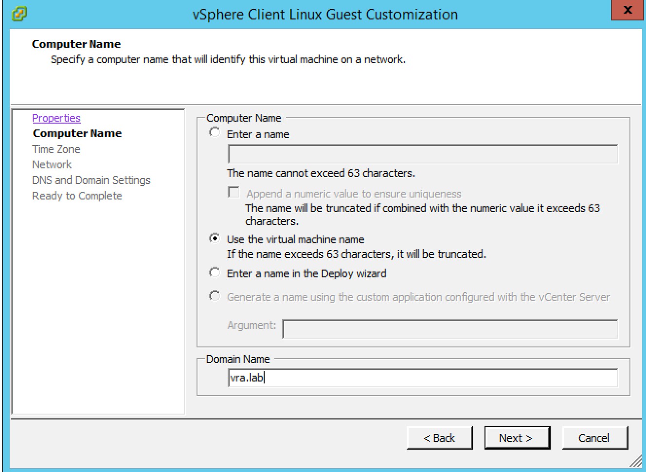
Fig 12: Setting up the computer name on a guest specification
When setting up the virtual machine template, don’t forget to install the VMware tools, otherwise the cloning will not take place.
Prepare for provisioning
In order to configure provisioning based on a linked or full clone, perform the following steps:
- On a vSphere machine template, change to the Build Information
- Select Server or Desktop from the Blueprint type dropdown list.
- Choose Clone or Linked Clone from the Action dropdown list.
- In the Provisioning workflow dropdown list, choose CloneWorkflow (the only choice).
- Choose the template or snapshot, from which your virtual machines should be created.
- Optionally, choose a Customization spec. The customization spec must be created in vSphere in advance. Please note that you have to type in the exact name of this specification.
- Click Finish.
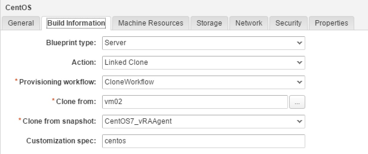
Fig 13: Configuring Linked Clone provisioning
Fig. 13 shows the graphical user interface for configuring the provisioning workflow.
| Hint: Data collection
We have mentioned it before, but as it is a common source of confusion, we want to repeat that here again. If you have just created a template in vSphere, it might not yet show up during the blueprint configuration. In that case, don’t forget to trigger a data collection on the corresponding compute resource. |
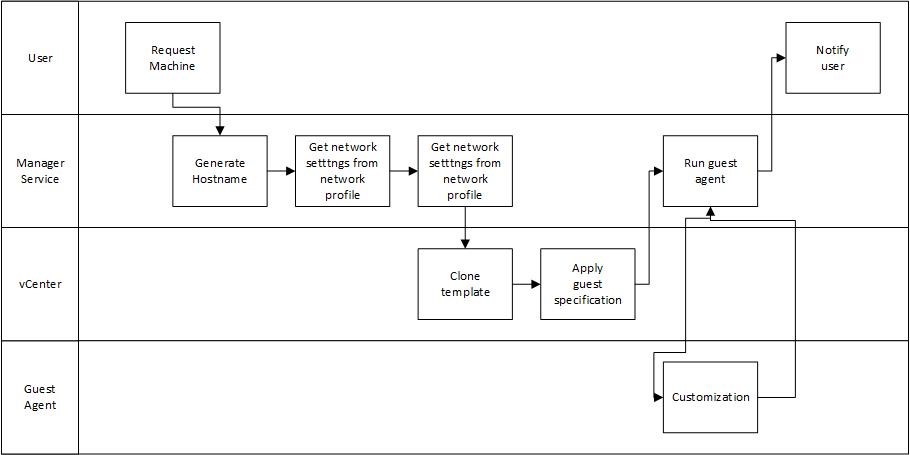
Fig 14: vSphere Cloning workflow
Fig. 14 shows the workflow that vRealize Automation internally uses to provision a virtual machine based on cloning.
9.2.3 NetApp Flex Clone
Another alternative for fast provisioning is the NetApp Flex Clone. However, this workflow can only be used if you are using vSphere in combination with a NetApp storage solution. The configuration is quite similar to the Clone workflow, but there are some prerequisites:
- You have to create and configure a NetApp-ONTAP endpoint.
- The reservation must be configured for the use of Flex Clone.
Once you have done this, you can use the Flex Clone workflows. Compared to Linked Clones, Flex Clones have some advantages. One of the main characteristics of linked clones is that they require their base disks to reside on the same datastore as the delta disks. Furthermore, with Flex Clones there is support for hardware offloading. This means that all the copying is essentially done by the storage array and vSphere would not be involved in copying. However, so far Flex Clones are only supported on NFS datastores, VMFS datastores are currently not supported.
9.2.4 Linux Kickstart
The Linux kickstart workflow helps to automate the provisioning of Linux machines. However, there are a couple of steps that have to be taken in order to get the Linux kickstart workflow running.
9.2.4.1 Preparing the Linux boot ISO
In nearly every Linux distribution, a bootable image can be created via the isolinux tool. Most of the CentOS DVDs already ship with the isolinux tool. This can be used as a basis for creating the boot ISO. Once you have mounted the DVD, you need to extract the folder and then edit the isolinux.cfg. The following snippets shows the configuration for CentOS 6.5:
#Begin isolinux.cfg
default vesamenu.c32
timeout 1
menu title Welcome to CentOS 6.5!
label linux
menu label ^Install or upgrade an existing system
menu default
kernel vmlinuz
append initrd=initrd.img network –device=eth0 –bootproto=dhcp ks=https://yourwebserver.cfg
#End isolinux.cfg
Please customize the isolinux.cfg according to your needs (change the webserver and also ensure that the network card setting is correct). Next, navigate to the directory containing the isolinux folder and execute the following command:
genisoimage-r –T –J –V “RHEL6AMD64” –b isolinux/isolinux.bin –c isolinux/boot.cat –no-emul-boot –boot-load-size 4 –boot-info-table –o /working/RHEL6X64.iso /working
The file boot.cat will be created by the command. This is the catalog needed for the boot loader. The file isolinux.bin is the image of a boot loader. The output file will be RHEL6x64.iso.
If you want to create the bootable image in Windows, there are also free tools available, for example ImgBurn.
9.2.4.2 Creating the kickstart config
The next step is to create a kickstart config file. Fortunately, there is already a sample configuration file that can be used as a starting point. To locate the file, download and unpack the LinuxGuestAgent package and then locate the subdirectory which corresponds to the operating system you wish to deploy. Open the sample-https.cfg file in an editor. The file looks like this:
auth –useshadow –enablemd5
bootloader –append=“rhgb quiet“ –location=mbr –driveorder=sda
zerombr
clearpart –all –initlabel
text
firewall –disabled
keyboard us
lang en_US
logging –level=info
network –bootproto=dhcp –device=em0 –onboot=on
reboot
rootpw secret
selinux –enforcing
timezone –isUtc America/New_York
install
part / –asprimary –fstype=“ext3″ –size=4096
part swap –asprimary –fstype=“swap“ –size=512
%packages
vim-enhanced
%post
function process() {
while true; do
/usr/bin/gugent –host=dcac.example.net –ssl –config=/usr/share/gugent/gugent.properties –script=/usr/share/gugent/site
if [ $? -eq 0 ]; then
break
fi
sleep 30
done
}
rpm -i http://rpm.example.net/rhel6-x86/gugent.rpm
export AXIS2C_HOME=axis2
export PYTHONPATH=/usr/share/gugent/site/dops
pushd /usr/share/gugent
echo | openssl s_client -connect dcac.example.net:443 | sed -ne ‚/-BEGIN CERTIFICATE-/,/-END CERTIFICATE-/p‘ > cert.pem
process # SetupOS
process # CustomizeOS
popd
The kickstart file configures a lot of things, e.g. the root password, locale settings, partitioning of the guest machine’s hard disk and the installation of the guest agent on that machine. We will now discuss how to understand and modify the file according to your needs:
- In particular, all instances of the string host=dcac.example.net must be replaced with an IP address of a fully qualified domain name with a port number being set for the vRealize Automation server host.
- Also, modify the address within the rpm-command, where the rpm file can be downloaded.
- The url-parameter specifies where to download the installation files from. If you skip this parameter, it will search for the sources in the default location (the CD-ROM). In our case, we are downloading the packages from a web server, so make sure that all the files are accessible and downloadable.
- The post-section takes care of the guest agent installation (which will take place after the initial installation). It will first download the guest agent rpm and then install it. Internally, the guest agent uses Axis2 (an old SOAP web service framework) and Python, which are also configured in the script. The last step is to download the vRealize Automation Server IaaS certificate (the communication between the guest and the agent must be trusted).
9.2.4.3 Verifying DHCP settings
Once you have created the bootable ISO image, and finished and uploaded your kickstart file, we have to make sure that there is a DHCP server available on the network, so that our new Linux instance will receive an IP address and can boot safely.
9.2.4.4 Configuring the machine template
The last step is to configure the machine template on the blueprint. Follow the steps outlined to setup the Linux kickstart workflow:
- Change to the Build Information tab on the machine template.
- Select Create from the Action dropdown menu.
- Choose LinuxKickstartWorkflow from the Provisioning workflow dropdown menu.
- Click on the Properties
- Add the following custom properties to the machine template:
- Image.ISO.Name: For vCenter Server, define the path to the ISO including the file name (use forward slashes for the directory separator). If you are using Hyper-V, take the full local path to the ISO file (including the file name). For Xen Server, use the name of the ISO file.
- Image.ISO.Location: Type the location of the bootable ISO image that you have created.
9.2.5 Microsoft SCCM provisioning
Deployment based on a SCCM workflow can be configured with vRealize Automation as well. What essentially happens is that vRealize Automation boots a newly provisioned machine from an ISO image. This later passes control to a SCCM task for the further installation and configuration steps. Before the SCCM workflow can be used, a couple of prerequisites have to be met:
- The NetBIOS name of the SCCM host is required and must be resolvable from at least the DEM.
- vRealize Automation and the SCCM server must be on the same network.
- A SCCM software page, which includes the vRealize Automation guest agent, must be installed.
- The SCCM package must install the vRealize guest agent.
- The SCCM files must be packaged as a bootable ISO.
- The bootable ISO must be accessible to the network.
Once these requirements have been met, we can continue with the blueprint configuration:
- Within the machine template, click the Build Information
- Select Create from the Action dropdown menu.
- Select VirtualSccmProvisioningWorkflow from the Provisioning workflow dropdown menu.
- Click the Properties
- Add the following custom properties to the machine template:
- Image.ISO.Location: Type the location of the bootable ISO image that you have created.
- Image.ISO.Name: Provide the location and the name of the ISO image.
- SCCM.Collection.Name: The SCCM collection name.
- SCCM.Name: The name of the SCCM file.
- SCCM.Server.SiteCode: SCCM site code.
- SCCM.Server.UserName: The SCCM username.
- SCCM.Server.Password: The SCCM password.
9.2.6 WIM provisioning
The Windows Imaging File (WIM) provisioning is certainly the most complex one to configure. There are several reasons for that. First, there are quite a lot of prerequisites which need to be fulfilled. Second, maintaining a template based on WIM provisioning is time consuming and complex. Third, it can only be applied to Windows machines. Last but not least, the provisioning time itself is quite long.
On the other side, there are also some benefits. Once you have WIM provisioning running, it can be used in nearly all environments, not only in vRealize Automation. If a company already has some experience in WIM, it only takes a short time to configure it in vRealize Automation. WIM also allows to easily customize hardware settings like CPU, memory or disk sizes. Also, adding user or groups to the image is straightforward.
From a technical point of view, WIM is a file-based image format that was developed by Microsoft in order to deploy operating systems in distributed systems. WIM images must be provisioned on existing volumes respectively. WIM itself does not provide a tool for creating such volumes or partitions, it is up to the user to take care about that (however, there is a tool from Microsoft named diskpart, which creates and formats partitions).
In order to create a WIM image, you also need the ImageX command line tool (which is part of the Windows Automated Installation Kit).
9.2.6.1 Preparing for WIM provisioning
The following steps must be completed in order to configure WIM provisioning:
- First of all, a staging area has to be configured. This staging area will be used to upload the required files for the provisioning process. The staging area must be accessible from vRealize Automation as well as from the machine being provisioned. The preferred way to communicate with the staging area is using a network drive or an UNC path.
- A DHCP server is needed as well.
- To create the template, a Windows reference machine must be installed.
- Once the reference machine is created, you can sysprep the machine using the System Preparation Utility.
- The WIM image can be created after having sysprepped the Windows machine.
- Usually, additional scripts should be invoked after the WIM provisioning. This can happen using the PEBuilder tool, which is provided by vRealize Automation. The best way is to install the tool on a dedicated development machine and store all the scripts to be invoked as apart of the provisioning process. The PEBuilder installation files can be found on the vRealize Automation appliance (URL: https://<vra-app.domain.name>:5480/installer). You need Microsoft .NET 4.5 and the Windows Automation Installation Kit (AIK) as a prerequisite. The scripts to be invoked should be placed in the Plugins\VRM Agent\VRMGuestAgent\site\work item subdirectory of the PEBuilder installation directory.
- Create a WinPE image using PEBuilder and insert the guest agent into the WinPE image as follows:
- Run PEBuilder.
- Enter the host name of vRealize Automation into vCAC Hostname
- Type the vCAC Port.
- Enter the path of the PEBuilder plugin directory.
- Type the output path for the ISO file in the IOS Output Path text box.
- Click File > Advanced.
- Select the Include vCAC Guest Agent in WinPE ISO
- Click OK.
- Click Build.
- Upload the WinPE image to the staging environment.
Once the WIM image has been created and all the other prerequisites have been completed, we can continue with the configuration of the machine template on the blueprint:
- On the machine template, click the Build Information
- Select Create from the Action dropdown menu.
- Select WIMImageWorkflow from the Provisioning workflow dropdown menu.
- Click the Properties tab.
- Add the following custom properties to the blueprint:
- Image.ISO.Name: For vCenter Server, define the path to the WinPE ISO, including the name (the value must use forward slashes), for Hyper-V use the full local path to the WinPE ISO file, including the file name, for Xen Server use the name of the WinPE ISO file.
- Image.ISO.Location: Type the location of the bootable ISO image that you have created.
- Image.WIM.Path: The UNC path to the WIM file.
- Image.WIM.Name: The name of the WIM file.
- Image.WIM.Index: The index to be used to extract the desired image from the WIM file.
- Image.Network.User: The username under which to map the WIM image path (Image.WIM.Path) to a network drive.
- Image.Network.Password: The associated password for the network user (Image.Network.User).
9.3 Provisioning of cloud machines
From time to time, it is required to provision resources onto the cloud. Similar as with virtual machines, vRealize Automation must be prepared in order to be able to configure machine templates for the cloud. These steps involve storing credentials and creating endpoints, bringing resources under vRealize Automation management, configuring business groups and managing reservations. In the previous chapters, we have already shown how to perform these steps, so it is now time to configure the blueprint.
vRealize Automation supports the following platforms for cloud provisioning:
- vCloud Director[1]
- Amazon AWS
- Open Stack (Icehouse, Juno, Kilo)
- VMware Integrated OpenStack
- vCloud Air
vRealize Automation provides a set of provisioning workflows in order to configure blueprints for cloud deployments. The following table shows these workflows:
| Workflow | Platform | Description |
| CloudProvisioningWorkflow | Amazon
OpenStack |
Provision resources to Amazon and OpenStack |
| vAppCloneWorkflow | vCloud Director | Clone vApp templates in vCloud Director |
| CloudLinuxKickstartWorkflow | OpenStack | Kickstart/autoyast |
| CloudWIMImageWorkflow | OpenStack | Windows Imaging Format |
Fig 15: Cloud provisioning workflows
9.3.1 Provisioning with Amazon AWS
The following issues must be considered when configuring vRealize Automation for Amazon AWS:
- The cloud machine templates are mapped to Amazon Machine Images (AMIs).
- The selected AMI of the machine template must be accessible from vRealize Automation.
- The requester’s user account muss be added to the EC2 instance – after the provisioning has taken place – in order to be able to log on the machine.
With that knowledge in mind, we can configure our blueprint for using Amazon (see Fig. 16).
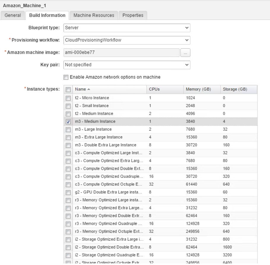
Fig. 16: Configuring a AWS machine template
- From the tool pane on the left-hand side of the blueprint designer, drag and drop an Amazon machine template to the main pane.
- On the machine template, click the Build Information
- Select the Blueprint Type.
- From the Amazon machine image drop down list, click on the […] button and select the Amazon machine image (AMI) that you want to provision (Caution: There can be many AMIs available – according to your permissions – and filtering is not possible).
- Specify the Key pair settings: Not specified (uses the settings of the reservation), AutoGenerated per Business Group or AutoGenerated per Machine.
- Setting the Enable Amazon network options on machine tick allows end users to decide if they want to provision their resources onto a VPC or non-VPC environment. Only set this checkbox if your AWS account really supports EC2-classic provisioning.
- The table Instance types lets you choose a list of instance types that can be provisioned by end users.
As you have seen, the Amazon instance types are already listed on the machine template designer. You can see the default instance types by navigating to Infrastructure > Administration > Instance Types and optionally add new instance types, delete or edit them (see Fig. 17 ).
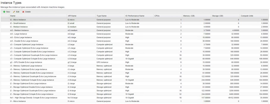
Fig. 17: Instance types
9.3.2 Provisioning with OpenStack
In order to be able to provision resources to OpenStack, endpoints, reservations and blueprints must be prepared in a similar way to other resources. Most of the steps are the same, so we will only concentrate on the differences. First of all, an OpenStack endpoint must be created:
- Select Infrastructure > Endpoints > Endpoints.
- Select new Endpoint > Cloud > OpenStack.
- Enter a name and a description.
- Type the URL in the Address The format must be FQDN:5000 or IP:5000.
- Select the credential for the endpoint.
- Type a tenant name in the OpenStack project text box.
- Click OK.
The other steps (including fabric groups, reservations, machine prefixes and business groups) do not differ that much from the configuration as described before, hence we will not focus on them again.
Currently, vRealize Automation allows for provisioning with virtual machine images, Linux kickstart, or WIM provisioning. The third provisioning mechanism – virtual machine image provisioning – comes in two forms:
- Virtual Machine Images are templates that contain a software configuration including an operating system.
- OpenStack flavors define compute, memory and storage capacity of computing instances. In other words, a flavor is an available hardware configuration for a server. It defines the size of a virtual server that can be launched. Flavors are similar to instance types in Amazon.
Finally, the template on the blueprint can be configured:
- From the tool pane on the left-hand side of the blueprint designer, drag and drop an OpenStack machine template to the main pane.
- On the machine template, click the Build Information
- Select the Blueprint Type.
- Select which workflow to use, from the Provisioning workflow drop down list. As described earlier, OpenStack offers the CloudWIMImageWorkflow, the CloudProvisioningWorkflow and the CLoudKickstartWorkflow.
- Choose an OpenStackImage.
- Specify how to generate a key pair: Not specifed (uses the settings of the reservation), Auto Generated per Business Group or Auto Generated per Machine.
- Define the flavors of the blueprint.
9.3.3 Provisioning with vCloud Air
vRealize Automation can provision vCloud Air resources as well. Essentially the same preparation steps are required:
- Create a vCloud Air endpoint.
- Bring the resources under vRealize Automation management.
- Configure the IaaS features such as fabric groups, reservations or business groups.
- Create blueprints.
| Amazon AWS vs vCloud Air
While Amazon is the leader in the public cloud market, deploying to vCloud Air can also be an interesting alternative. Because this is a book about a VMware product, we want to address how vCloud Air differs from Amazon AWS and what the advantages are: First of all, vCloud Air comes with automatic redundancy – hot standby redundant capacity is included and it’s free. Virtual machines are monitored by default. If a failure occurs, the machine is automatically restarted with the same network configuration (IP addresses, MAC addresses, etc.). While resiliency is possible with Amazon, too, it is not an out-of-the-box feature, so it must already have been considered while designing the application. vCloud Air datacenters monitor their hosts and in case a machine is overloaded, virtual machines automatically get live migrated to other machines. However, with Amazon, from time to time, resource congestions happen at the hosts. One of the principles of AWS is that everything can fail. Therefore, you must design your application with that in mind. When there is a problem with an Amazon host or maintenance work is done, virtual machines in AWS might be switched off at very short notice. vCloud Air, on the other hand, migrates machines to other hosts before doing any maintenance work. vCloud Air is also more flexible in terms of instance sizes. You can have any VM size and can even resize the machine (VM or disk), while it’s running. Hardware resizing is not possible with AWS – you have to switch the instance type, which means additional administrative work. Most companies have vSphere running in their on-premise network. When moving machines to vCloud Air, no conversion is needed. Furthermore, as on- and off-premise environments are based on the same vSphere technologies, you can keep your app support. Cloud Air allows stretched layer 2 networks between your data center and vCloud Air. This can be done with Direct Connect, a dedicated link between your datacenter and vCloud Air. Because it is a layer 2 network, it appears like a single flat LAN segment. Amazon – on the other hand – also offers Direct Connection access to their datacenters, however they are using IP (layer 3) network connectivity. |
With vRealize Automation 7, it is now much easier to connect to vCloud Air compared to prior versions. There is now a dedicated vCloud Air endpoint. When creating an endpoint for vCloud Air, the address will automatically populate with the vCloud Air public address you are familiar with. In terms of a blueprint authoring experience, setting up a vCloud Air machine template is now in line with other machines such as AWS or vSphere. The vCloud Air machine template supports the provisioning via cloning.
Fig. 18 shows the blueprint designer with three different vCloud Air machine templates configured.
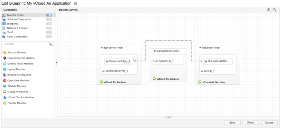
Fig. 18: Setting up vCloud Air machine templates
| Hint: vApps in vRealize Automation 7
In vRealize Automation 6 together with vCloud Director or vCloud Air, vRealize Automation supported vApps as well as vApps components. In vRealize Automation 7, this has changed: It is no longer possible to nest a component within a vApp. Instead, if you drag different vCloud Air machine templates onto the blueprint designer canvas and even connect them to the same network (in this case, you have to use custom properties – as the network tab is only visible on vSphere machine templates), the deployment will result in different vApps and not in one vApp with two machines. |
9.3.4 Provisioning with vCloud Director
The last provisioning mechanism to be discussed is vCloud Director. Similar to other mechanisms, the following preparations steps are required:
- Create a vCloud Director endpoint.
- Bring the resources under vRealize Automation management.
- Configure the IaaS features such as fabric groups, reservations or business groups.
- Create blueprints.
Internally, vCloud Director uses vApps as a container entity for provisioning resources. A vApp consists of different component machines that are provisioned and managed as a single entity. Besides acting as a container for the different components, a vApp can also take care of network provisioning. While vRealize Automation can trigger the provisioning of vApps, using vCloud Director, it does not inherently know about the concept of vApps. As you know, vRealize Automation uses multi-machine blueprints, whose functionality can be compared to vApps. The following table compares both approaches (see Fig. 19).
| vRealize Automation blueprint | vCloud Director vApp |
| Blueprint acts as a container for blueprints | Based on vApp templates |
| Provisioning of virtual and cloud machines | Only cloud machines can be deployed |
| Machines are managed by vRealize Automation | vApps can be managed by vRealize Automation |
| Access:
Microsoft Remote Desktop SSH VMware Remote Console |
Access:
Microsoft Remote Desktop SSH VMware Remote Console |
| Network provisioning based on VMware NSX | Network provisioning is an out-of-the-box capability of vApp |
| After provisioning, additional machines can be added | Machines cannot be added after provisioning |
| Boot order of the virtual machine is defined within the multi-machine blueprint | vApp determines start order |
Fig 19: Blueprint vs. vCloud Director vApp
When setting up a vCloud Director endpoint, consider the following issues:
- When providing the address for the endpoint, the URL is in the format https://fqdn.
- If you only want to access a specific organization within vCloud Director, use organization administrator credentials. You can then add a dedicated endpoint for each organization.
- If you want to allow access to all organizational vDCs in the vCloud Director instance, use system administrator credentials and leave the Organization text box empty.
The rest of the configuration is in line with the other provisioning mechanisms, so we will not cover the configuration details here.
9.4 Summary
This chapter described how to set up blueprints in vRealize Automation. First, we showed how to create a blueprint and configure the basic settings of a blueprint. In the remainder of the chapter, we have shown how to configure the different provisioning workflows.
[1] check the exact versions at: http://www.vmware.com/resources/compatibility/sim/interop_matrix.php
Recent Comments