
We have shown you in the last chapter by which means and tools vRealize Automation can be extended. We will now dig into how to implement new functionality. This chapter will cover the vRealize Automation Designer. The following chapters will cover vRealize Orchestrator and the Advanced Service Designer.
19.1 The vRealize Automation IaaS model
Before creating workflows for IaaS provisioning, it is first crucial that you understand the IaaS model and thus are able to modify its values as required. In chapter 2 we introduced the Model Manager and explained how Microsoft SQL server is used to store its data. However, working with the database directly is (in most cases) not recommended – instead, vRealize Automation provides helper methods in order to deal with this data. Nevertheless, there is a good tool available to explore the IaaS model – LINQPad[1]. Once you have installed the tool (a Windows system with .NET is needed), you can explore the IaaS model:
- Start the LINQPad tool.
- In the navigation area at the upper-left side of the screen, click Add Connection and choose WCF Data Services 5.5 (OData 3).
- Type the following URI to connect to your server:
- Check the Accept invalid certificates
- Click OK (see Fig. 1).
Once a connection has been established, LINQPad shows all the IaaS entities on the left-hand side of the screen. Besides showing entities, LINQPad also provides a wizard to create and execute LINQ queries. For example, you can create a query by right clicking on an entity and selecting the first function <Entity name>.Take(100). LINQPad then executes the query and shows the result set within the main area of the screen (see Fig. 2).
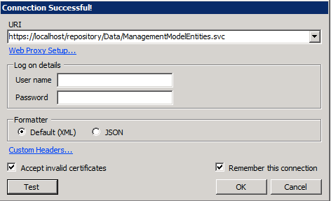
Fig. 1: Using LINQPad to connect to the Model Manager
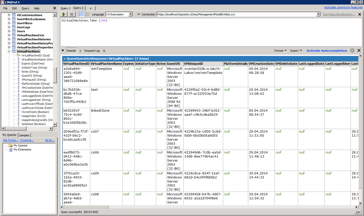
Fig. 2: Executing a query in LINQPad
There are many different entities within the vRealize Automation Model Manager – for example virtual machines, users, reservations or build profiles. However, you must also bear in mind that the Model Manager only stores IaaS data – everything else is stored within the vPostgres database on the Linux appliance.
Each entity in vRealize Automation has a set of properties. Entities are usually linked to each other. For example, there might be different pending requests for a user, or a virtual machine has different VirtualMachineProperties. Relationships between entities are indicated with a fork-icon. There are three different relationships: One-to-One, One-to-Many and Many-to-One.
| Background: LINQ
LINQ (Language Integrated Query) is a Microsoft technology. It is part of the .NET framework. The syntax resembles SQL, however LINQ is more powerful in terms of querying data. For example, when querying more than one entity at the same time, there is no join-statement required – instead, you can traverse between entities by using the “.” operator. LINQ supports lambda-expressions as well. Lambda-expressions are anonymous functions, which can be used on result sets for sorting, filtering or grouping. The following statements show how to use LINQ Queries: Query for a virtual machine named “vm1”: from vm in VirtualMachines where vm.VirtualMachineName = “vm1” Query for all compute resources including the credentials of the endpoints: from hosts in Hosts.Expand(“ManagementEndpoint/Credential”) select host |
19.2 vRealize Designer
The first step to using vRealize Designer is – of course – to install it. You can download the Designer from the vRealize Appliance website (https://<vrealize-automation-appliance.domain.name>:5480). Like the IaaS services, the designer requires Microsoft .NET to be preinstalled. Also, before you start the installation, you must have the address of the vRealize Automation service and the Model Manager ready with you. Please also note that the tool needs an open connection to your vRealize Automation environment at runtime. Once you have completed the installation, you can start the tool (see Fig. 3). The graphical user interface of this tool is quite intuitive. The ribbon menu bar only offers a small number of commands. These include options to load, save, open or send workflows.
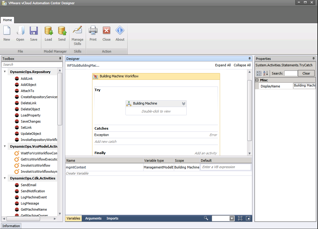
Fig 3: vRealize Designer
Most work is carried out in the main pane – that’s where you can develop your workflows. A workflow consists of many smaller tasks. These are arranged sequentially and connected via arcs.
On the left-hand side of the screen is the toolbox. It contains a variety of tasks, grouped into the following categories:
- Repository: Tasks within this category are used to access the entities within the vRealize Automation model. You can use this category as well, if you want to invoke another workflow stored in the Model Manager.
- VcoModel.Activities: The enclosed tasks are used for interaction with vRealize Orchestrator. With the latest releases of vRealize Automation, these tasks have become less important. vRealize Orchestrator and vRealize Automation can now interact with each other independently, without the need to create a special workflow in vRealize Designer.
- The Cdk.Activities category provides a variety of tasks, including logging, sending emails or retrieving information about virtual machines.
- The ControlFlow and FlowChart categories provide programming constructs for: flows, decisions or if-statements.
- Basic programming tasks are encompassed within the Primitives For example, there are tasks for assigning variables, invoking methods, or outputting something to the console.
- If you need access to arrays or collections, the Collection category provides some helper tasks.
- For error handling there is also a dedicated category.
You can define the basic structure of your workflow by dragging & dropping elements from the toolbox into the main pane. Once an element has been placed within the designer pane, it must be configured. This can be done by selecting the appropriate element in the main pane. On the right-hand side of the screen, there is a Properties window. Here configuration settings can be actioned.
Tasks within the designer pane must always be connected to a workflow. Therefore, you must use arcs to connect them with other elements. A minimum workflow always has a start element and an end element – so if you add additional tasks, you have to place them within these nodes.
Another very important concept of vRealize Designer is the use of variables. Variables are needed to pass information between different tasks. For example, if there is a task that reads the content of a script file and a second that executes the script, then a variable is needed to store the script content and pass it to the next task. Variables have a context, which decides the visibility of the variable. For example, global variables can be read and modified everywhere, whereas a local variable is only defined within a certain area and may not be touched from outside of this area.
Workflows, within vRealize Designer, are not invoked by vRealize Automation. Instead it happens as part of the machine’s lifecycle (for example during provisioning) or based on user interaction within the self-service catalog. In both cases, the workflow needs some input regarding the context in which it is called. This contains information regarding which virtual machine is concerned and/or what kind of action was invoked. To store this information, each workflow must provide a set of variables. Here the aforementioned information can be found. Variables can be found in the lower part of the screen.
It is important to note that vRealize Designer allows modification of existing workflows, but does not permit creation of new ones (see Fig. 4-5). However, there is a set of existing workflow stubs that can be used to implement the required workflow logic. There are workflow stubs for the following purposes:
- Workflows that can be invoked from an action on a blueprint.
- Workflows that can be run during the machine’s lifecycle. For example, the BuildingMachine, MachineDisposing, MachineExpired, MachineProvisioned, MachineRegistered and UnprovisionMachine stage is supported.
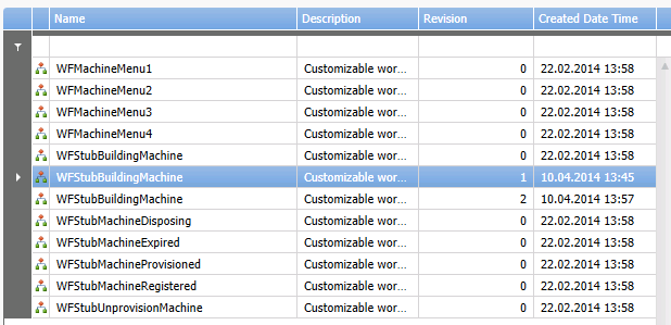
Fig. 4: Workflow stubs
| Hint: Cloudutil utility
If you want to upload files to the Model Manager, you can use the cloudutil.exe command. The cloudutil.exe file can be installed as part of the vRealize Automation Designer. You will find the installation files on the IaaS-installer page. Once you have installed the vRealize Automation Designer, go to the directory C:\Program Files (x86)\VMware\vCAC\Design Center and run the following command to upload your script (replace with your script name and file): Cloudutil.exe FileImport –n MyScript -f MyScript.ps1 |
When creating a workflow, from time to time there is also a need to upload additional fragments such as PowerShell scripts, configuration files or any other files. This can be done with the cloudutil utility.
After having given a small introduction to the foundations of vRealize Designer, it is time to become more practical and show how to use the designer tool itself.
19.3 Use case: Invoke a PowerShell script as part of the provisioning process
In this scenario, we will write a small script that will be uploaded to the Model Manager. This can then be invoked from a vRealize Designer workflow during the provisioning of a virtual machine. The script used in this example is simple, but you could replace it with a more complex one in your environment.
First, open the PowerShell-ISE or an equivalent editor on your computer and paste the following code fragment:
$Hostname = $Properties[“VirtualMachineName”]
## script logic begins here
Write-Host $Hostname
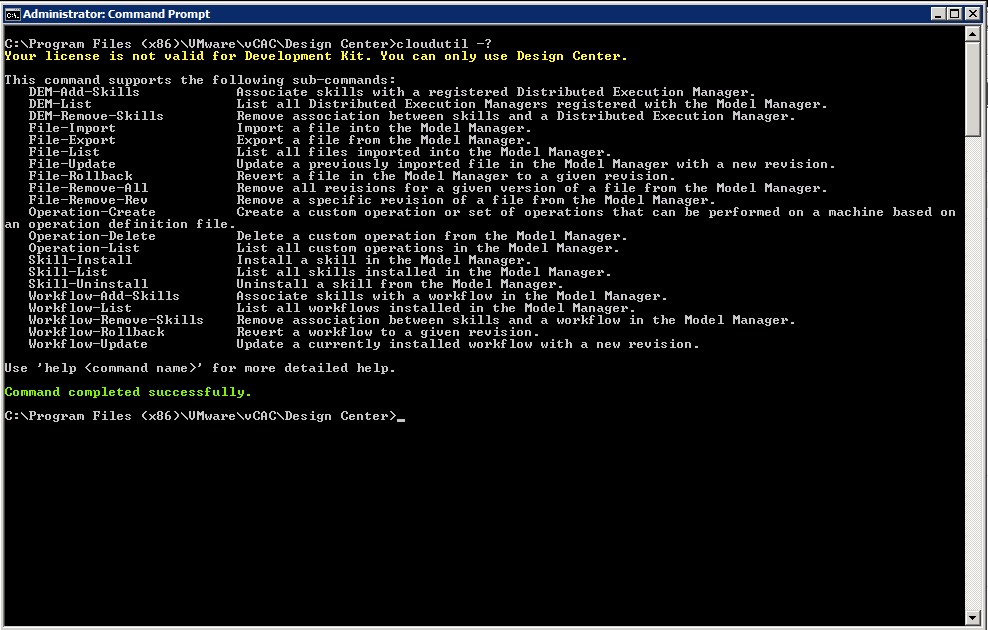
Fig 5: Cloudutil.exe utility
Once finished, save the script on your desktop computer and perform the following steps on a machine with the vRealize Designer installed:
- Open the command prompt and change to the C:\Program Files(x86)\VMware\vCAC\Design Center.
- N.B.: You can upload your PowerShell script by using the Cloudutil-tool. Type the following command (see Fig. 5):
Cloudutil.exe File-Import –n &lt;name of the file used for the vRealize Automation repository&gt; -f &lt;PowerShell script file&gt;
- You can check if your upload was successful by using the exe File-List command. Please check if you find your uploaded file within the list of the repository.
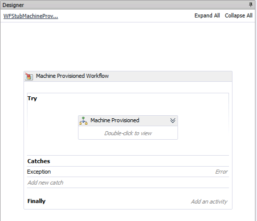
Fig 6: Editing a workflow stub
19.3.1 Implementing the workflow
Now we can begin with the implementation of the workflow. Start the vRealize Designer and follow the steps as described below:
- Within the ribbon menu, click the Load button and select the WFStubMachineProvisioned workflow. We will be customizing this workflow and it will be run after a machine has been provisioned. Click OK. After a short while, you will see the stub of the workflow (see Fig. 6).
- Double-click on the Machine Provisioned You will see that there is some nested content now shown in the main pane (see Fig. 7).
- The workflow consists of different tasks to be run in a sequential order. After a start element, there is a logging element to output some basic information over the workflow. The next task (Create ManagementModel Context) will open a connection to the Model Manager. After that there is another nested element (Custom Code). This is the workflow fragment, in which your customization code takes place. To edit, double click this Custom Code element.
- The custom code element begins with a start element, too. Remember, our scenario requires to read the content of a PowerShell script file and then run that code. Our PowerShell script file expects the hostname as a parameter and will output this hostname to the console. Consequently, we need to somehow grab the name of the virtual machine that has been provisioned. Unfortunately, we do not have the name. Our workflow stub only receives the GUID (Global Unique Identifier) of the virtual machine provisioned (see Fig. 8). However, there is a task within vRealize Designer, that can get us the name of a virtual machine when provided with its GUID. This task is called GetMachineName. Consequently, locate the GetMachineName task within the toolbox on the left-hand side of the screen and drag & drop it to your workflow below the start element.
- Now we need to connect both elements. When you hover over the start element, you will see some grey boxes appear at its borders. Click on such a square and drag the arrow to the GetMachineName node (see 14-10).
- Now we must consider how to deal with the GetMachineName task. The task will receive the GUID as an input and return the name of the virtual machine as an output. As we require this name for a later task, we must first create a variable to contain its value. In order to achieve this, first click the Create Variable button within the lower variables section and then assign vmName as a variable name. The definition of the variables is depicted in Fig. 10.
- In the next step, we can configure the GetMachineName We have to set the GUID as an input parameter and the newly created variable as an output parameter. Double click on the element and configure the element as shown here (see Fig. 11):
Machine Id: “VirtualMachineId” Machine Name: “vmName” - Next, we should load the content of the PowerShell script. Our PowerShell script receives a single variable as an input. However, as a PowerShell script can receive multiple parameters, passing the input as dedicated variables is not suitable – instead an array is used to pass arguments. This means we must create a new variable. Therefore, within the variables section, click on Create Variable and name it args. Change the type of the variable by clicking on Browse for Types within the Variable Types column (see Fig. 12).
- Now, another dialog opens, in which you have to specify the exact data type. The PowerShell script expects this input as a variable of type Collection.Generic.Dictionary <TKey, TValue>. This is a dictionary, where the TKey and TValue define the data type of the key and the data type of the value respectively. Within the Type Name textbox, enter the dictionary data type und use String for both TKey and TValue (Fig. 13 shows how to configure this).
- Before we can pass the args-variable to the PowerShell task, we must first enter the name of our virtual machine. This is done with the help of the Assign Locate the appropriate task within the toolbox, drag & drop it below the GetMachineName element and connect it with the aforementioned task.
- Configure the Assign-task (see Figs. 14-15):
To: “args(“VirtualMachineName”)” Value: “vmName” - Finally, we can invoke the PowerShell script. There is a special activity called ExecutePowerShellScript, which allows us to do that. Drag & drop the element from the toolbox and connect it with the Assign task (see Fig. 15).
- Like other elements, the ExecutePowerShell task needs proper configuration, too (see Fig. 16):
Script Name: The name of the script which was specified during the Cloudutil upload Machine Id: “VirtualMachineId” Arguments: “args” - Now that the implementation of the workflow has been finished, we only have to save it. Click the Send button within the ribbon menu in order to do so.
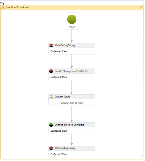
Fig. 7: MachineProvisioned nested workflow
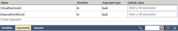
Fig. 8: Workflow arguments
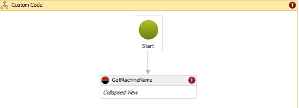
Fig. 9: Get the machine name
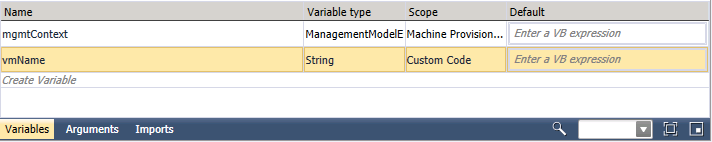
Fig. 10: Defining variables
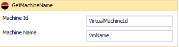
Fig. 11: Configuring the GetMachineName task
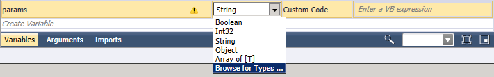
Fig. 12: Defining the Input parameters for the PowerShell script
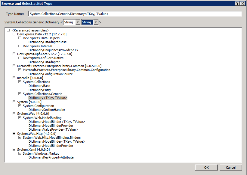
Fig. 13: Choosing a datatype
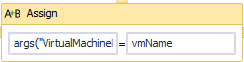
Fig. 14: Configuring the Assign task
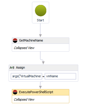
Fig. 15: Workflow for executing a PowerShell script

Fig. 16: Configuring the ExecutePowerShellScript task
| Background: Workflows in vRealize Designer
Workflows in vRealize Designer usually encompass a lot of different tasks. However, these tasks do not usually fit on the screen and thus can be nested. Nevertheless, vRealize Designer tries to show all tasks in a clear manner. This means arranging the elements on different levels. When you open a workflow, you will see the top-level element first (the Machine Provisioned Workflow in our scenario). It will contain a try-catch clause, which encloses a Machine Provisioned Element. The try-catch clause element is a very powerful construct in programming languages. If any error occurs within the try-clause, the control flow will automatically jump to the catch-clause and will execute any exception handling code. Therefore, if any error occurs, at the very least you want to be notified, hence a logging statement is reasonable. If you expand the Machine Provisioned element, you will see the structure of the workflow (see Fig 17): Each workflow has a start and an end node. Before running any custom workflow logic, a log statement first logs basic information regarding the actual workflow instance. In parallel, a connection to the vRealize Automation repository is opened. Your custom logic takes place within the Custom Code task. Once this task has been successfully executed, the state of the workflow changes to ‘complete’ and the workflow ends with the creation of a log statement. |
Once we have finished the implementation of our workflow, we still have to tell vRealize Automation when to run it. This can be achieved at the blueprint level:
- Open the blueprint that needs to be configured for this workflow and switch to the Properties tab.
- Assign a new property named MachineProvisioned
- Don’t enter a value for the property.
- Click OK to save your changes.
Background: How to activate workflows
We have shown you how to setup a blueprint which runs a workflow using custom properties. This does not only apply to MachineProvisioned workflows, but also to all other workflows. Use the following custom properties, for the other workflow types:
- WFStubBuildingMachine: ExternalWFStubs.BuildingMachine
- WFStubsMachineDisposing: ExternalWFStubs.MachineDisposing
- WFStubUnprovisionMachine: ExternalWFStubs.UnprovisionMachine
- WFStubMachineRegistered: ExternalWFStubs.MachineRegistered
- WFStubMachineExpired: ExternalWFStubs.MachineExpired
19.4 Additional Workflow activites
Besides the activities covered in this scenario, there are a lot of other tasks available. At this point, we want to introduce the most important ones:
- CreateRepositoryServiceContext: Establishes a context with the vRealize Automation Model Manager.
- AddLink/DeleteLink: Creates/Deletes a relationship for objects.
- SetLink: Connects two entities with a link.
- AddObject/UpdateObject/DeleteObject: Activities for creating, updating or deleting entities.
- UpdatesObjekt: Persists a object. Must be called after an AddObject/DeleteObject invocation.
- AttachTo: Adds a new object within the context.
- LoadProperty: Loads a property.
- InvokeRepositoryWorkflow: Invokes a workflow.
- SaveChanges: Persist changes, must be called after an update.
- ExecuteSshScript: Invokes a SSH script
- GetMachineName: Loads the machine name of a virtual machine.
- GetMachineProperties: Loads all properties of a machine.
- GetScriptForName: Loads the content of a script stored in the Model Manager.
- InvokePowerShell: Invokes a PowerShell script.
- InvokeSshComand: Executes a SSH statement.
- LogMachineEvent: Writes an entry into the userlog of the machine owner.
- LogMessage: Writes to the DEM log.
- RunProcess: Runs a process.
- SendEmail: Sends an email.
- SetMachineProperty: Modifies a machine’s custom property.
- SetWorkflowResult: Changes the state of the workflow.
19.5 Summary
This chapter covered installing and using the vRealize Designer. The designer was the preferred tool for customization before vRealize Orchestrator gained support for vRealize Automation. Right now, in vRealize Automation, it remains largely as a tool for backwards compatibility. Therefore, we recommend using vRealize Orchestrator instead of vRealize Designer for implementing any new workflows. vRealize Orchestrator is covered in the next chapters.
[1] LINQPad can be purchased, but there is also a cost-free version for download at http://www.lingpad.com
Recent Comments