
13.1 Overview
After having described what NSX is useful for and having outlined the benefits of an integration of NSX into vRealize Automation, it is now time to focus on the practical implementation. In particular, this chapter will focus on the following issues:
- Preparing NSX for vRealize Automation
- Using Orchestrator to set up endpoints
- Editing the vSphere endpoint in order to communicate with NSX
- Discussing network profiles
- Deploying NSX blueprints
- Using security groups on blueprints
13.2 How to prepare NSX for vRealize Automation
At this point, we are presuming that you have a working NSX environment including a valid VXLAN configuration, segment IDs and a transport zone. If not, there are plenty of tutorials[1] available on the internet. Once this has been done, we can begin with the configuration for vRealize Automation. In particular, we have to configure the following components:
- A Provider Edge Gateway that is connected to the boundaries of your network.
- A Distributed Logical Router (DLR) with a single uplink to the Provider Edge.
- A Logical Switch that connects both the Distributed Logical Router and the Provider Edge.
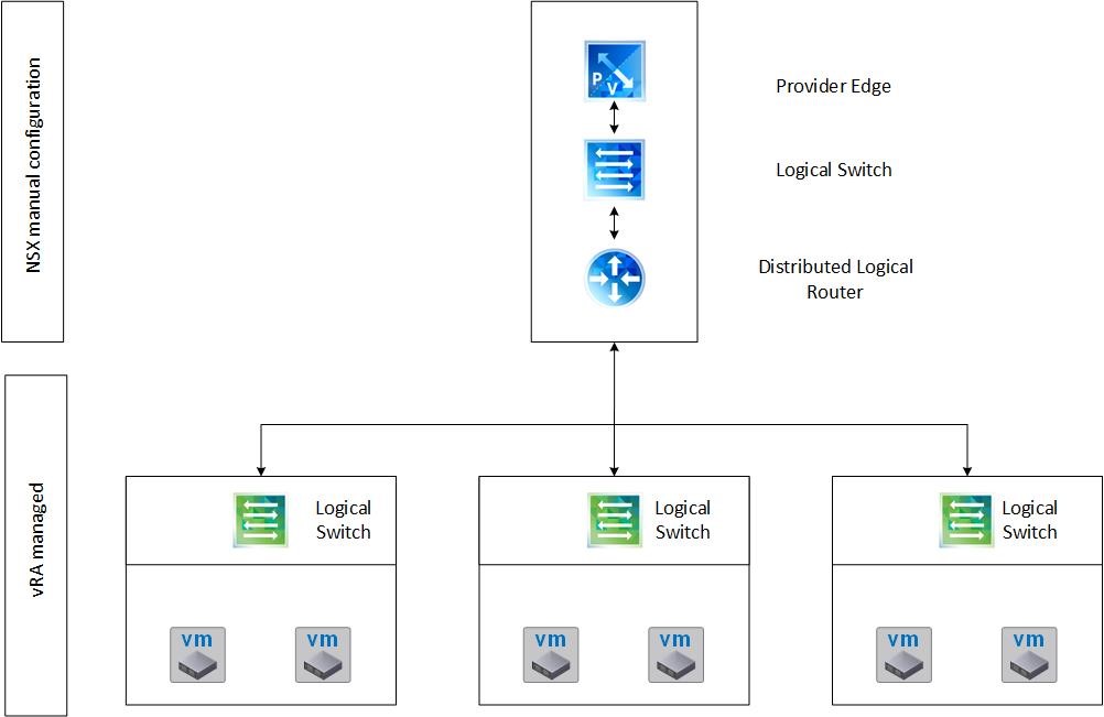
Fig 1: NSX and vRealize Automation integration overview
At runtime, vRealize Automation uses Orchestrator to dynamically create new Logical Switches and connect them to the DLR. Fig. 1 shows this configuration.
13.2.1 Creating a logical switch
The steps to create a logical switch can be described as follows:
- Log in into the VMware vSphere Web Client.
- In the Navigator pane, select Networking & Security and then Logical Switches.
- From the NSX Manager dropdown list, select the appropriate NSX Manager.
- Click the [+] button to create a new Logical Switch.
- Provide a Name, a Description, the Replication mode (most likely Unicast) and check the Enable IP Discovery
- Click OK to create the Logical Switch.
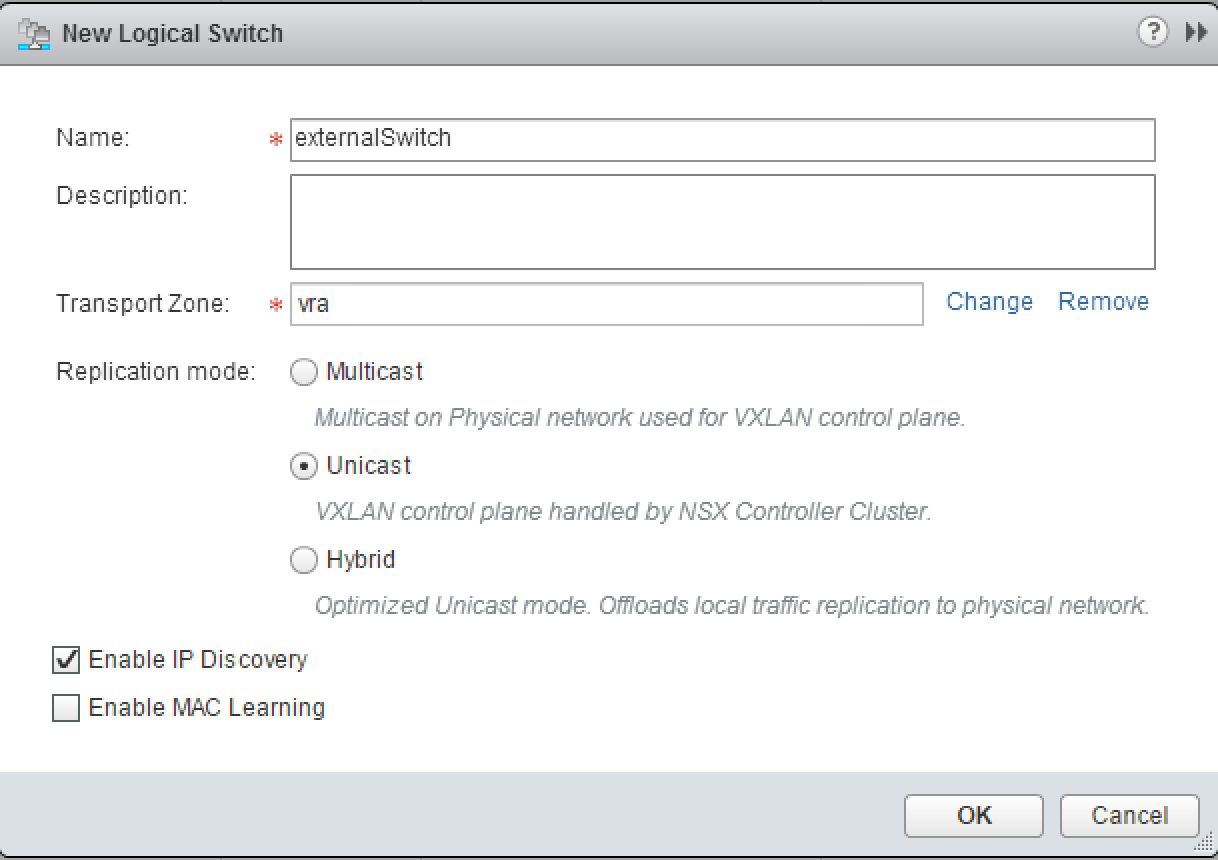
Fig. 2: Creation of a Logical Switch
13.2.2 Creating the provider edge gateway
The next step is to create the Provider Edge Gateway. The edge needs to have two uplinks. One will be connected to the external boundaries and the other one to your internal network. This can be done as follows:
- In the Navigator pane, navigate to the NSX Edges
- From the NSX Manager dropdown list, select the appropriate NSX Manager.
- Click the [+] button to create a new edge.
- Check the Edge Services Gateway checkbox and optionally provide a value for the Name, Description and Tenant.
- Check the Deploy NSX Edge checkbox and optionally the Enable High Availability Click Next.
- On the Settings page, define a Username and Password for the edge. Also review the settings for SSH and the logging level. Enable auto rule generation. Click Next.
- The next dialog configures the deployment. Choose the Datacenter where you want to deploy the edge. Also, define the Appliance Size.
- We also have to define the ESXi host, where the edge will be deployed. Click the [+] button and choose an ESXi server accordingly. Once finished, click Next.
- Now, it’s time to configure the interfaces. As discussed, we need an internal interface that is connected to the Logical Switch and an external one that is connected to the boundary of our network. Let’s begin with the outer one and click the [+]
- Provide the following input for the interface (see Fig 3):
- Name: e.g. externalUplink
- Type: Uplink
- Connected To: Your distributed port group that was created as a prerequisite
- An IP address with a Subnet Prefix Length
- MTU: 1500
- Click OK
- Repeat step 10 for the second interface, but choose Internal as Type. Once finished, click Next.
- On the Default gateway settings page, check the Configure Default Gateway checkbox, choose your uplink interface and provide the Gateway IP along with the MTU Click Next to continue.
- On the Firewall and HA page, review the settings for the firewall default policy and continue with Next.
- On the last screen, Ready to complete, review your settings and click Finish. NSX will start the deployment process of the provider edge.
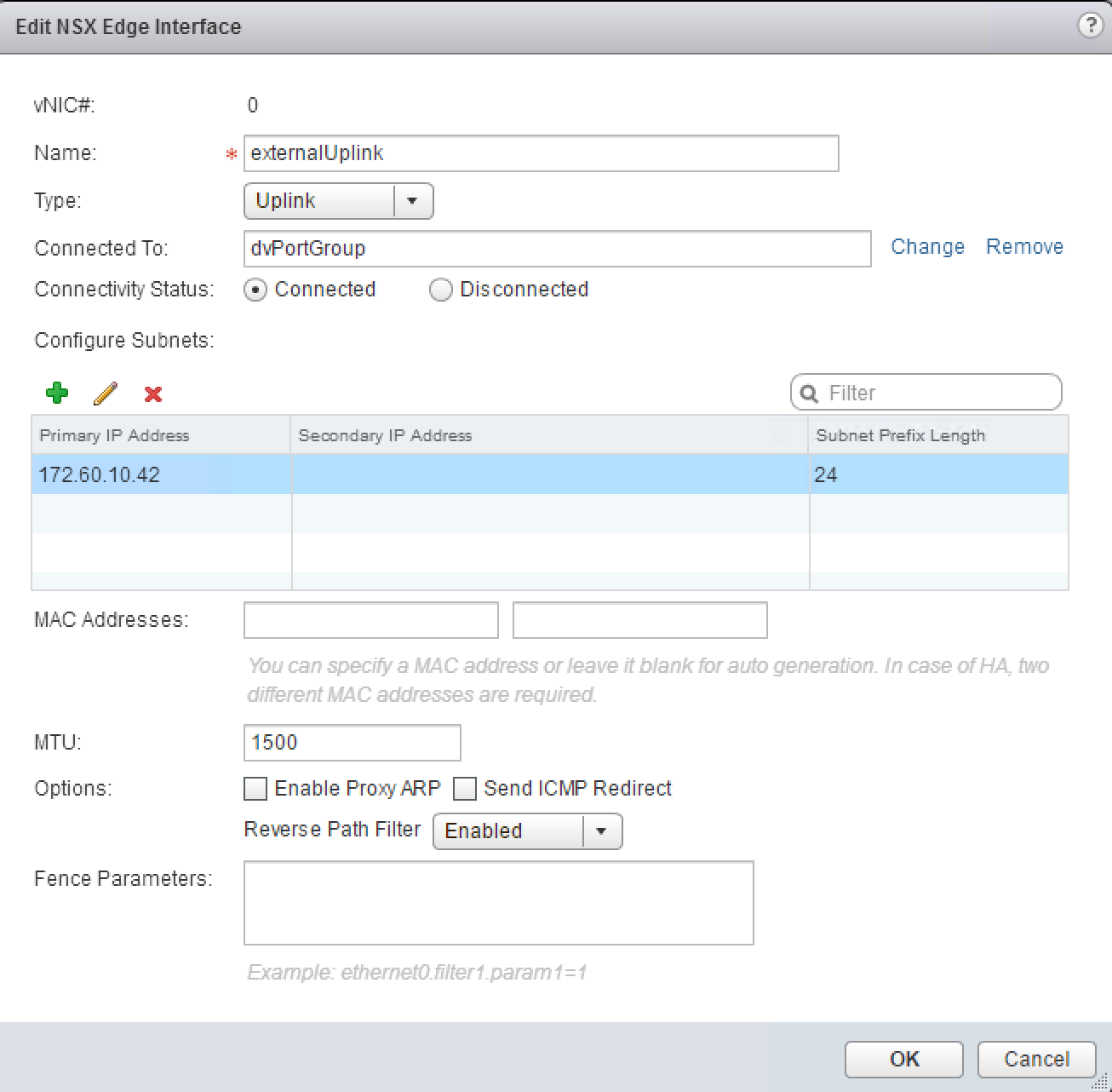
Fig. 3: Adding an interface to an edge
13.2.3 Creating the distributed logical router
The last step within the manual configuration is to create the DLR. The DRL will be connected to the Provider Edge via the Logical Switch, so we need one uplink configured. The creation process is pretty similar to the creation of the Provider Edge:
- In the Navigator pane, navigate to the NSX Edges
- From the NSX Manager dropdown list, select the appropriate NSX Manager.
- Click the [+] button to create a new edge.
- Check the Logical (Distributed) Router checkbox, provide a Name and optionally a value for the Description and Tenant.
- Check the Deploy NSX Edge checkbox and optionally the Enable High Availability Click Next.
- On the Settings page, define a Username and Password for the edge. Also review the settings for SSH and the logging level. Enable auto rule generation. Click Next.
- The next dialog configures the deployment. Choose the Datacenter where you want to deploy the edge. We also have to define the ESXi host, where the edge will be deployed. Click the [+] button and choose an ESXi server accordingly. Once finished, click Next.
- Now, it’s time to configure the interface. As discussed, we need an uplink interface that is connected to the Provider Edge. Click the [+] button and provide the following values:
- Name: e.g. externalUplink
- Type: Uplink
- Connected To: The Logical Switch created before
- An IP address with a Subnet Prefix Length
- MTU: 1500
- Click OK.
- On the Default gateway settings page, check the Configure Default Gateway checkbox, choose your uplink interface and provide the Gateway IP along with the MTU Click Next to continue.
- On the last screen, Ready to complete, review your settings and click Finish. NSX will start the deployment process of the DLR.
13.3 Using Orchestrator to set up an NSX endpoint
The next step in the configuration process has to be done in Orchestrator. At this point, we assume that you have a working instance of Orchestrator running in your environment. If not, you can read about the basics of Orchestrator in chapter X.
Perform the following steps to create an NSX endpoint in Orchestrator (you can skip these steps if you are working in a small environment with only one Orchestrator instance):
- Open the Java Orchestrator Client.
- Change to the Run mode (in the upper area of the screen) and then to the Workflows pane (on the left-hand side of the screen).
- In the Workflow library navigate to the Library > NSX > Configuration
- Run the Create NSX endpoint
- On the Common parameters, provide input for your NSX environment and click Submit:
- Endpoint name
- NSX username: admin
- NSX password
- NSX URL
If you want to verify the NSX endpoint, you can now change to the Inventory tab and expand the NSX node. If everything works fine, you should be able to see all your NSX components in the NSX hierarchy (see Fig. 4).
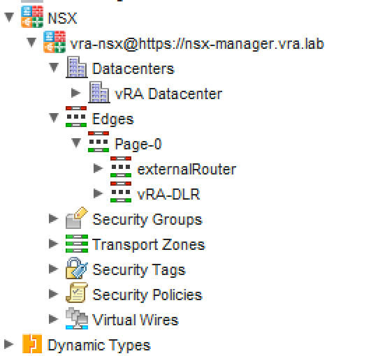
Fig. 4: NSX hierarchy in Orchestrator inventory view
13.4 Editing the vSphere endpoint
The last step in the configuration process is to modify the vSphere endpoint in the vRealize Automation user interface. However, before starting, please consider that you need the Orchestrator endpoint working correctly in order to perform these steps (we will cover how to configure the Orchestrator configuration in a later chapter, however, Fig. 5 shows the endpoint configuration of the internal Orchestrator appliance for the moment). Perform the following instructions:
- Log in into vRealize Automation as an Infrastructure administrator.
- Navigate to the Infrastructure > Endpoints > Endpoints
- Hover over your corresponding vSphere Endpoint and click Edit from the context menu.
- On the Edit Endpoint page, check the Specify manager for network and security platform
- Provide the Address for the NSX manager (see Fig. 6).
- Next to the Credentials textbox, click the […]
- If you already have stored your credentials for the NSX manager, select the credentials and click OK. Otherwise click the [+ New] button and create the credentials for the NSX manager. After having selected the appropriate credentials, close the dialog.
- Click OK to save the changes on the vSphere endpoint.
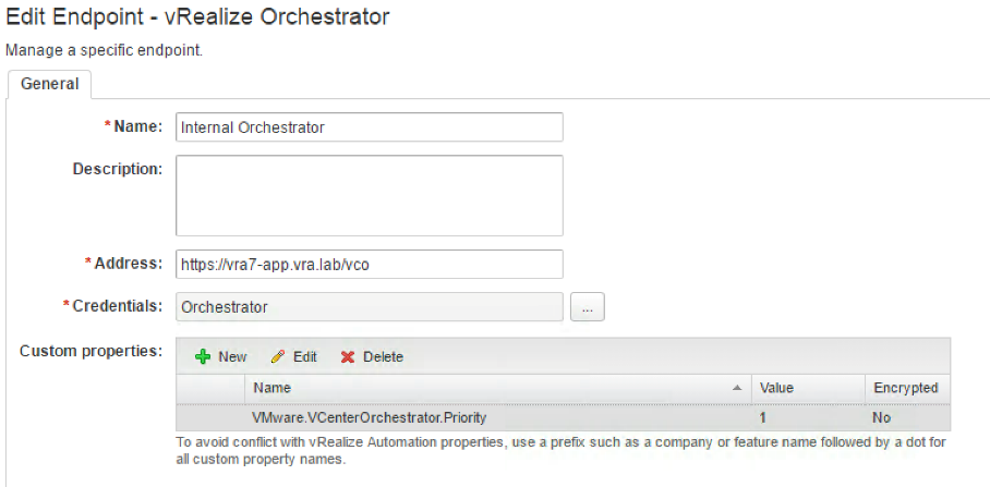
Fig. 5: Embedded Orchestrator endpoint configuration
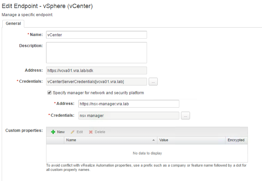
Fig. 6: Adding NSX to the vSphere endpoint
Once the configuration has been saved, vRealize Automation will start a data collection for the endpoint. You can validate the configuration by navigating to the Infrastructure > Compute Resources > Compute Resources page and opening the Data Collection of the vSphere endpoint. You will see the Networking and Security Inventory collection result at the bottom of the page. If anything has gone wrong, you can find a detailed error message on the log viewer (Infrastructure > Monitoring > Workflow History).
13.5 Network profiles
We have already covered network profiles in chapter 6 und 7. Network profiles help you with the network configuration of virtual machines. When a virtual machine is associated with a network profile on a blueprint, all relevant network settings can be deducted from the profile. If you don’t have NSX, those networks must be created beforehand.
From time to time, there is also the requirement to configure a network on the fly. However, this means not only automating the machine provisioning, but also the network provisioning. When deploying a complex multi-tiered application as described in the use cases before, additional components are needed: Logical switches and networks, security groups, firewalls, load balancers or firewall rules. Without being able to dynamically create networks, the provisioning of complex applications cannot be automated. Therefore, manual intervention is still required. When such a dynamic provisioning of networks is needed, vRealize Automation has to be integrated with VMware NSX.
13.5.1 Basics of network profiles
Essentially, network profiles perform two main functions in vRealize Automation. Firstly, they are responsible for the NIC configuration (i.e. IP address, subnet mask, default gateway, DNS). Secondly, in conjunction with NSX, they provide edge services router configuration (route or NAT functionality). There are four different principle types:
- External network profiles – provisioned machines get connected to a network, which is created and configured outside of vRealize Automation. You should work external network profiles if you have an existing network (VXLAN or VLAN backed) that you want connect dynamically created virtual machines or NSX edge gateways to.
- Routed network – vRealize Automation dynamically creates a network with different subnets and a routing table. Routed networks are a valid choice if there is end-to-end routable access with unique IP addresses needed.
- One-to-One NAT profile – Used to conserve externally routable IP addresses within a network. If have overlapping IP addresses across different blueprint deployments and external connectivity is needed as well, then a NAT profile is the one to choose.
- One-to-Many NAT profile – Similar to One-to-One NAT profile, however there is no destination NAT.
As stated, network profiles are responsible for the NIC configuration. They provide an easy way for virtual machines to reference IPs addressed to a machine during the lifecycle and provisioning through vRealize Automation. This in turn allows to reclaim IP addresses when the machine is eventually destroyed. This is a very handy feature for companies which do not have an IP address management (IPAM) tool like infoblox running.
The following points are required for vRealize Automation to successfully inject an IP address into a vSphere machine:
- Guest customization specification – IP addresses will be assigned using the guest customization specification. Without configuring this, IP addresses will be reserved from the pool, but they will not be applied to the provisioned machine.
- VMware tools – behind the scenes, the configuration of virtual machines with new IP addresses happens with the VMware tools.
As stated, the guest customization specification is required by the internal IPAM system. However, if this is not the case, you can still use the IPAM system, but additional work is required (you would have to configure the network device by yourself):
In general, when a VM is deployed with a network profile, the following custom properties are set:
- Network0.Address
- Network0.SubnetMask
- Network0.Gateway
- Network0.PrimaryDNS
- Network0.SecondaryDNS (optional)
- Network1.Address
- Network1.SubnetMask
- …
These custom properties could be read by an Orchestrator workflow, which in turn would invoke another workflow to assign the IP address using the Guest API (we will talk about Orchestrator in a later chapter in detail). If Orchestrator is not a valid choice, you could also place a script in the machine template. This script receives some input and configures the networking settings. In addition, using a software component would also be possible.
Depending on the desired functionality, you need to choose the appropriate network profile to be created. At this point, we will only focus on routed and NAT network profiles as external network profiles have already been covered in chapter 6 and 7.
13.5.2 Routed network profiles
As stated, you use a routed network profile when there is a need for end-to-end routable access with unique IP addresses. When deploying a blueprint with a routed network profile embedded, vRealize Automation will instruct NSX to connect the newly created network to the existing DLR and configure the DLR in such a way that the newly created network is routed to the upstream L3 gateway.
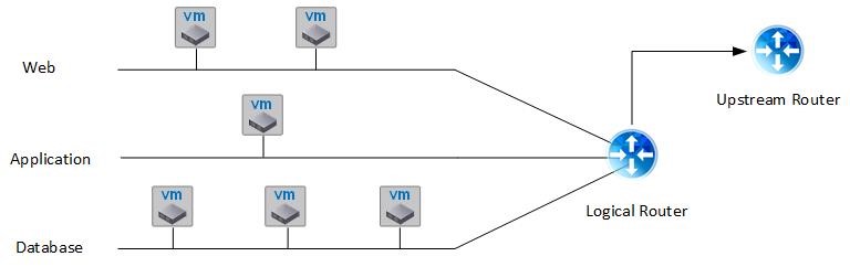
Fig. 7: Routed networks
Fig. 7 shows such a deployment based on a routed network profile. The deployment has three different tiers with each tier being connected to the DLR.
In order to get a routed network profile running, the following steps must be done:
- Set up an external network profile for the upstream.
- Set up the routed network profile.
- Add the network profile to the corresponding reservation.
As we have already covered how to set up an external network profile in chapter 7, we will not show those configuration steps in details.
13.5.2.1 Setting up an external network profile
The process of external network profile creation is the same as described in chapter 7. However, please consider to use the DLR IP address as the external network’s gateway.
13.5.2.2 Setting up a routed network profile
To create a routed network profile, carefully work through the following tasks:
- Navigate to Infrastructure > Reservations > Network Profiles and hover over the [+ New] button and select Routed. The configuration page opens (see Fig 8).
- Assign a Name for the network.
- Define a description (optional).
- Use the dropdown list External network profile to associate your network with a physical network.
- Specify a subnet mask (for example 255.255.0.0).
- Configure the range subnet mask. The range subnet mask determines how many networks will be created. For example, typing in 255.255.240.0 implies creating 16 networks, because the third quadruple specifies 4 bit for the amount of networks.
- Assign a Base IP address to specify the first network.
- Review or provide input for the Primary DNS, Secondary DNS, DNS suffix, DNS search suffix, Preferred WINS and Alternate WINS. Once you have connected your profile with an external network profile, these values automatically get pre-filled.
- Change to the IP Ranges tab to specify and review the IP addresses.
- Click OK to save your routed network profile.
13.5.2.3 Configuring the reservation
After the network profiles have been created and configured, you have to continue with the configuration of the reservations. We already introduced transport zones when talking about NSX. Transport zones can be discovered after an inventory scan, once the endpoints have been correctly configured for NSX. So at runtime, vRealize Automation is able to create the appropriate networks. In addition, you are able to configure
security groups. Security groups can be compared to firewalls between the different provisioned networks.
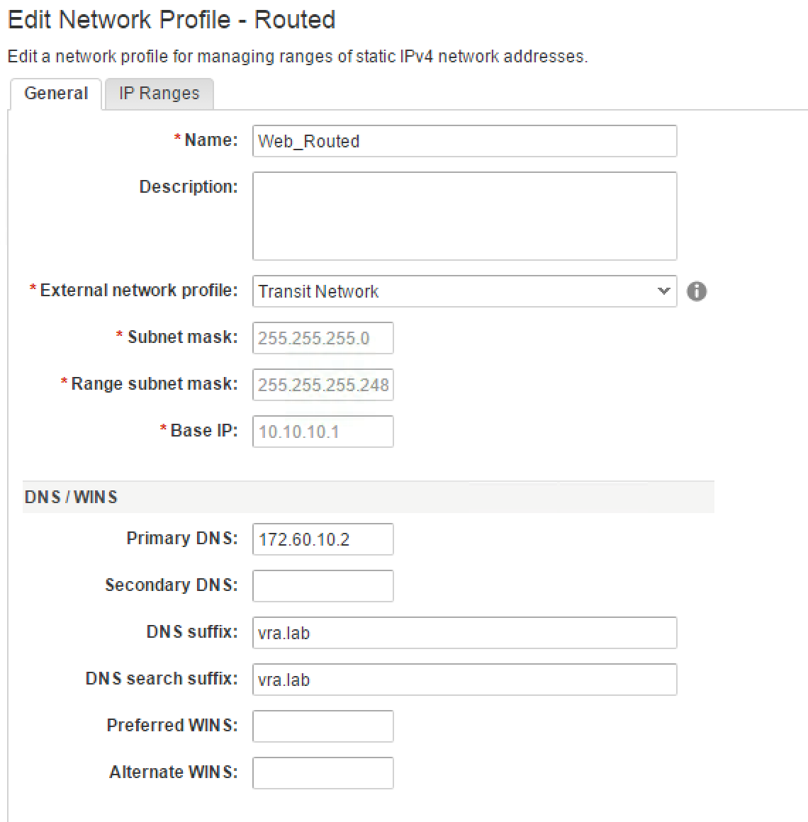
Fig. 8: Creating a routed network profile
When setting up a blueprint with a routed network profile, there must be a routed gateway to talk to the external network. This gateway is defined at the reservation level for routed and external profiles.
Run through the configuration, performing the steps as follows:
- Navigate to Infrastructure > Reservations > Reservations.
- Select and edit the reservation to which you want to apply the appropriate configuration.
- Change to the Network tab (see Fig. 9).
- As a first step, you must assign the external network. Within the Network Paths table, choose a network and select the appropriate network profile.
- Select the Transport Zone.
- When required, configure if you want to apply any security groups within the Security group list.
- To choose a routed gateway, activate the checkbox within the Routed Gateway table, choose a network path and assign an external network profile.
- Click on the Save
- Save your reservation with OK.
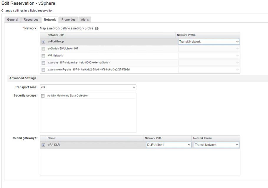
Fig. 9: NSX configuration for a reservation
13.5.3 NAT network profiles
The final kind of network profile that can be created, is the NAT network profile. A NAT network has similarities to a routed network, in that that it is connected to an external network via an edge gateway. NAT network profiles come in two different flavors:
- Within a One-To-One NAT network, each machine is assigned one IP address.
- A One-To-Many NAT network provides two IP addresses for a machine. For outgoing traffic, all virtual machines use the same IP address, however for ingoing traffic an additional address from the external network profile is used.
A NAT network is best suited for deploying identical networks. For example, if you want to provide a training environment for students or to have identical networks for the production/integration/testing of a network.
Behind the scenes, if you deploy a blueprint with a NAT network profile embedded, vRealize Automation will interact with NSX to deploy networks for the application connected to a newly deployed NSX Edge and instruct the DLR to route those networks to the upstream L3 gateway.
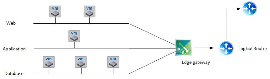
Fig. 10: NAT networks
The described scenario is depicted in Fig. 10. Similar to the routed network, when setting up a NAT network we need to have the external network profile configured first.
To create a routed network profile, we must complete the following steps:
- Navigate to Infrastructure > Reservations > Network Profiles and hover over [+ New] and select NAT. The configuration page opens (see Fig. 11).
- Assign a Name for the network.
- Define a description (optional).
- Use the dropdown list External network profile to associate your network with a physical network. When a network is deployed, the edge gateway will receive an IP address from the external network profile.
- Choose if you want to create a One-To-One or a One-To-Many NAT network type.
- Review or provide input for the Primary DNS, Secondary DNS, DNS suffix, DNS search suffix, Preferred WINS and Alternate WINS. Once you have connected your profile with an external network profile, these values automatically get pre-filled.
- Define the Subnet mask and the Gateway for the newly created networks.
- If you want to configure a list of assignable IP addresses change to the IP Ranges
- Click OK to save your routed network profile.
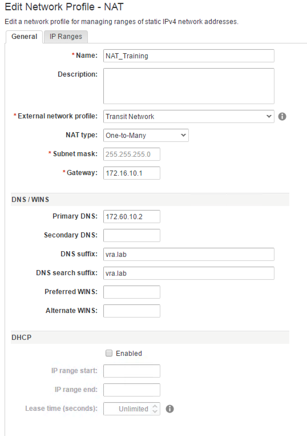
Fig. 11: Setting up a NAT network profile
13.6 Deploying NSX blueprints
After having discussed the NSX configuration and network profiles, it is now time to use NSX components on a blueprint and deploy a blueprint.
Readers of the previous blueprint chapters should be already familiar with the vRealize Automation blueprint design process, so we will only focus on the NSX networking parts her.
First, when creating a new blueprint, in the Blueprint Settings dialog, change to the NSX Settings tab and choose your Transport Zone. In addition, you can select a reservation policy for the Routed Gateway. Fig. 12 depicts the blueprint NSX settings.
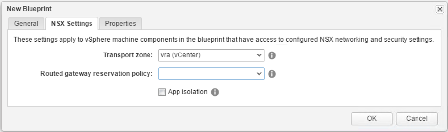
Fig. 12: NSX blueprint settings
With the blueprint designer open, you can now drag and drop your NSX components into the canvas. There is support for all the different network profiles:
- Existing network for an external network profile
- On-Demand NAT Network for a NAT network profile
- On-Demand Routed Network for a routed network profile
In addition, there is support for security tags, security groups and load balancers, which will be covered in the remainder of this chapter as well.
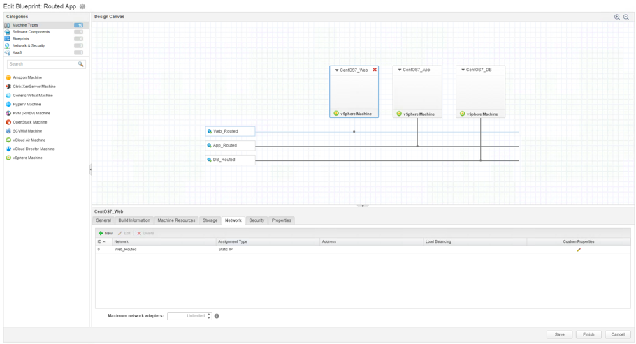
Fig. 13: Using NSX components on a blueprint
The further steps are easy to follow. Just add the network component to the blueprint, edit a machine template and select the appropriate network on the Network tab (see Fig. 13).
13.7 Using security groups on blueprints
In chapter 12, we have already introduced security groups. Security groups can also be used on vRealize Automation. Administrators can use security groups in two different flavors:
- First, existing NSX security groups can be used in a traditional way to create security tiers in vRealize Automation (e.g. web, app or database server).
- Second, there is support for on-demand security groups and firewall rules.
Let’s begin with the first scenario.
13.7.1 Using existing security groups in vRealize Automation
This approach basically creates security groups and firewall rules in NSX and applies them on vRA machines in a second step. Using this approach, you can block all communication between virtual machines inside of each tier – even when they are on the same subnet. For example, you can create a security group in NSX for each tier and then apply them on the different tiers of the blueprint.
Reviewing firewall rules in NSX
Before using security groups, you should review all firewall rules in NSX. Firewall rules can be configured in the vSphere Web Client by navigating to Networking & Security > Firewall. Fig. 14 shows the configuration of such rules.
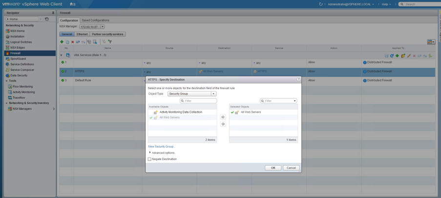
Fig. 14: Configuring firewall rules
Creating security groups
To create new security groups in NSX you can change to the Service Composer page and click the New Security Group button in the menu bar. A wizard will open, which lets you define the dynamic membership as well as the objects to include and exclude (see Fig. 15).
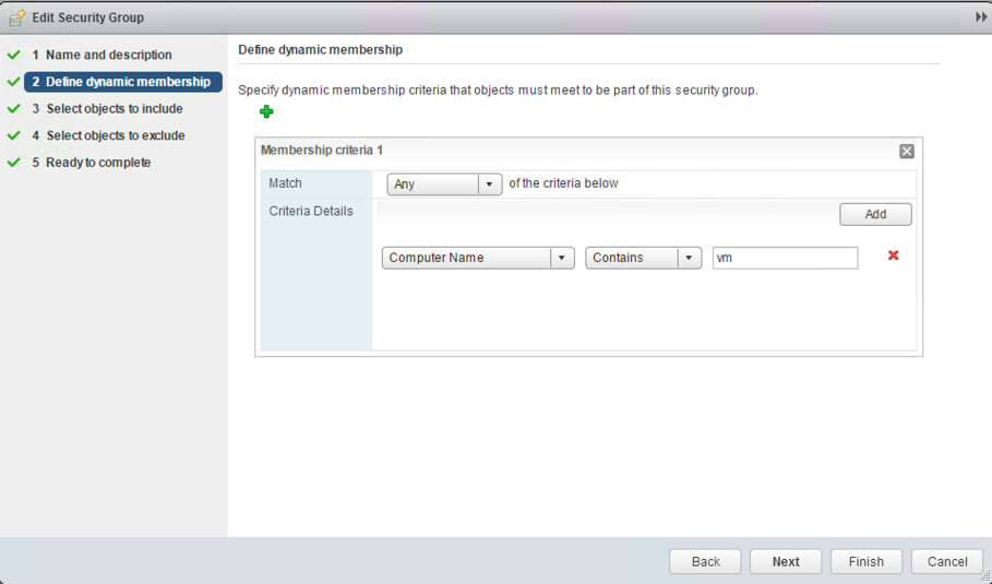
Fig. 15: Editing a security group in NSX
Once, you have created a security group, you can add firewall rules to it (this can be done on each firewall rule by referencing the security groups in the Source and Destination column – see Fig. 14 again). Using this mechanism, each security group corresponds to a tier.
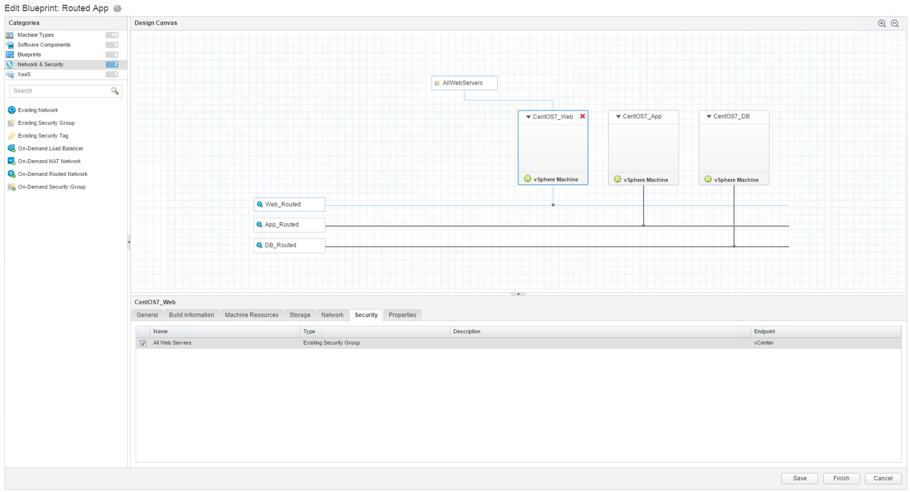
Fig. 16: Adding a NSX security group to a blueprint
Using security groups in vRealize Automation
Once the configuration work in NSX has been done, we can go back to vRealize Automation. However, before being able to reference the security groups, don’t forget to perform a data collection on the underlying vSphere compute resource. Once this has been successfully accomplished, we can open the blueprint designer again and perform the following steps:
- From the Categories menu, select Network & Security.
- Drag and drop the Existing Security Group element on the design canvas.
- Select the security element and choose your appropriate Security Group on the General
- Select the machine template where you want your security group to be applied and change to the Security
- Activate the checkbox to assign the security group.
13.7.2 Using on-demand security groups
One disadvantage of the traditional approach of security groups is that even you can block traffic within a tier, traffic between the different tiers is not blocked. However, this can be done with on-demand security groups.
The basic idea behind this approach is to block all traffic between virtual machines by default. For each traffic type you want to permit a security group template has to be created in NSX. For example, if a web server needs to talk to an application server on port 8080, a dedicated security group has to be created and assigned. In short, by leveraging NSX templates, vRealize Automation can granularly allow any appropriate traffic between virtual machines and tiers. Hence, this approach offers inter-tier micro-segmentation. Not surprisingly, on-demand security groups are often used to create groups of virtual machines on a multi-machine blueprint.
Now let’s discuss the steps to implement this approach.
Changing the default rule in NSX
First, we have to change the default rule from Allow to Block. This can be done by navigating to Networking & Security > Firewall and then selecting the Default Rule. Then, click on the pencil next to the Allow label and change the Action to Block.
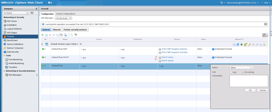
Fig. 17: Setting the default rule to Block
Creating security policies
The second step is to create a security policy for each type of traffic that acts as a template. A security policy is a collection of security services and/or firewall. Perform the following steps to create a security policy:
- Navigate to Networking & Security > Service Composer and create a new security profile.
- Within the New Security Policy wizard, move along to the Firewall sections and click the [+]
- Provide a Name and optionally a Description for the firewall rule.
- Choose Allow from the Action
- Set the Source as well as the Destination to Policy Security’s Group as the group memberships will be updated once machines with tagged security policies are provisioned .
- Specify the Service for the firewall rules.
- Set the State to Enabled and click OK (see Fig. 18).
- Click Finish.
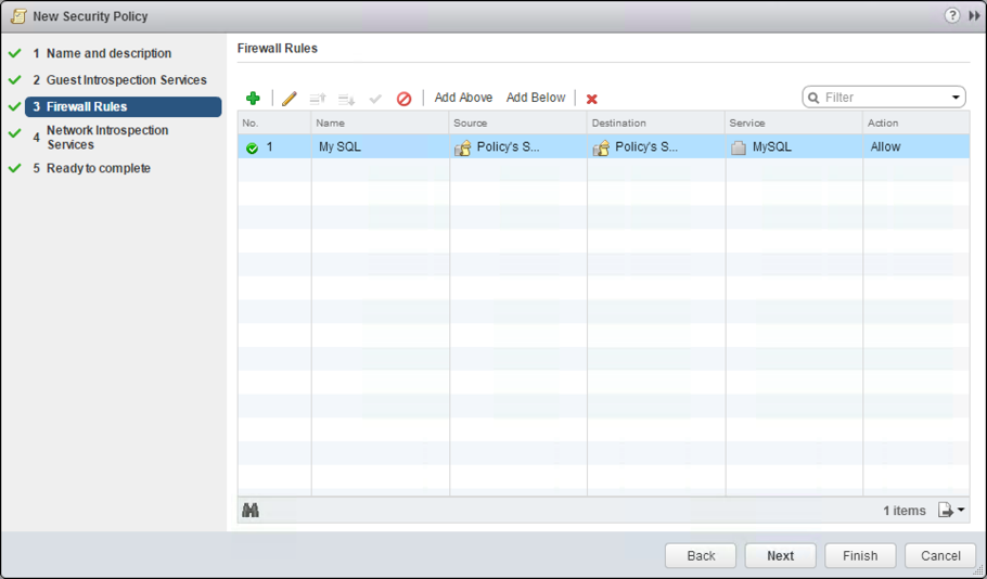
Fig. 18: Creating a security policy
Using an on-demand security group
Back in vRealize Automation, we first have to trigger a data collection on the underlying vSphere compute resource. Once this has been accomplished, we can use an on-demand security group on our blueprint. Perform the following steps:
- From the Categories menu, select Network & Security.
- Drag and drop the On-Demand Security Group element on the design canvas.
- Select the security element and choose your appropriate Security Policies on the General
- Select the machine template where you want your security group to be applied and change to the Security
- Activate the checkbox to assign the security profile.
- Click Save.

Fig. 19: Configuring an on-demand security group on a blueprint
13.7.3 Using App Isolation
So far, we have learnt about using existing security groups to control traffic within machines of a tier and on-demand security groups to set up rules for the traffic between the tiers. However, setting up such rules can be quite cumbersome, especially if you only want to isolate different deployments from each other. In that case, the App Isolation option provides an easy alternative. If enabled, machines that are part of the same blueprint deployment can talk to each other, while communication to machines in other deployments is prohibited.
To activate these settings, you only have to enable the App isolation setting on the Blueprint settings.
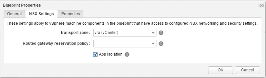
Fig. 20: Activating App isolation
13.8 Using Orchestrator for NSX
Another way to integrate NSX in vRealize Automation is to use Orchestrator. The Orchestrator NSX plug-in already ships with a set of workflows that can be used to implement your own custom logic. Fig. 21 shows the NSX workflows provided by NSX.
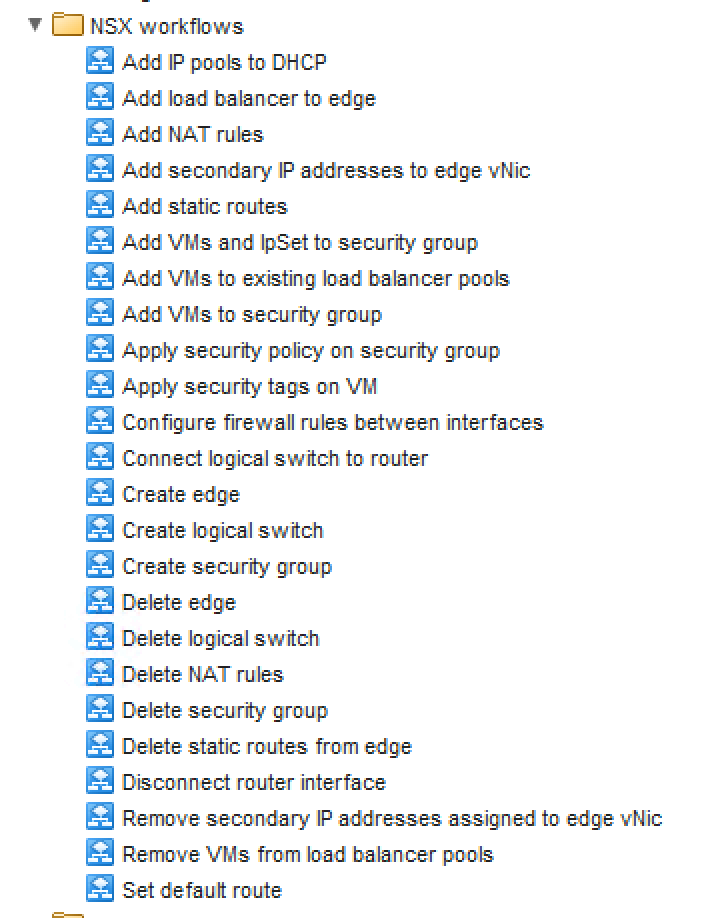
Fig. 21: NSX workflows in Orchestrator
13.9 Summary
This chapter showed how to integrate NSX into vRealize Automation. Once the configuration has been done, you can set up routed and NAT network profiles and configure your reservations to use them. The new blueprint designer now also supports the use of NSX component via drag and drop, hence setting up NSX on blueprints has become quite easy.
[1] A small and useful tutorial for setting up NSX can be found at http://vcrooky.com/sdn-and-nsx/
Recent Comments